Understanding Proximity Sensor Failure Modes
Proximity sensors are the silent sentinels of industrial automation, providing critical non-contact detection of metallic or non-metallic objects. However, like all electronic components, they have a finite lifespan and are susceptible to failure. Common failure modes include output signal degradation, where the sensor fails to switch reliably, often due to internal component aging or contamination of the sensing face. Physical damage from mechanical impact, vibration, or exposure to excessive heat can crack housings or damage internal circuitry. Environmental factors pose a significant threat; ingress of coolants, oils, metal shavings, or conductive dust can coat the sensing face or penetrate seals, leading to erratic behavior. Electrical issues, such as voltage spikes, incorrect wiring, or sustained overloads, can permanently damage the sensor's output stage. Recognizing these symptoms early—such as intermittent operation, failure to detect at the specified range, or a complete lack of output—is the first step in planning an effective replacement.
Pre-Replacement Checklist and Safety Protocols
Before initiating any replacement procedure, a systematic approach is paramount to ensure safety and accuracy. First, consult the machine's electrical diagrams and the specific sensor's datasheet to confirm its type (inductive, capacitive, ultrasonic), sensing range, output configuration (PNP/NPN, NO/NC), voltage rating, and connection method. Always adhere to Lockout-Tagout (LOTO) procedures. De-energize and isolate the entire machine or control circuit to prevent accidental startup or electrical shock. Use a multimeter to verify zero energy at the sensor's connection points. Document the existing wiring configuration with photographs or detailed notes, paying close attention to wire colors, terminal designations (Brown/+V, Blue/0V, Black/Output), and any shielding. Gather the correct replacement sensor and necessary tools: appropriate wrenches, screwdrivers, wire strippers, and possibly a mounting bracket. This preparatory phase minimizes downtime and prevents installation errors.
Step-by-Step Sensor Removal and Installation
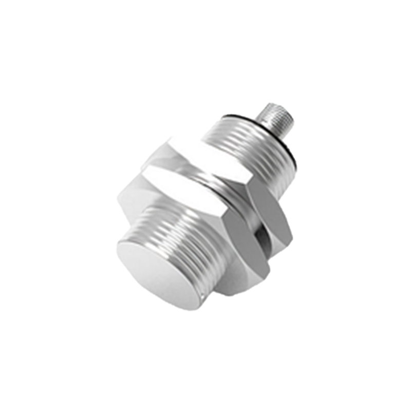
With safety confirmed and documentation in hand, proceed with removal. Disconnect the electrical connector or unscrew the cable gland to access the wiring terminals. Carefully loosen the mounting nut or screws that secure the sensor in its housing or bracket. Gently extract the old sensor, noting its orientation and any shims or spacers used for alignment. Before installing the new unit, thoroughly clean the mounting area to remove debris, oil, or metal particles. Compare the new sensor's specifications side-by-side with the old one to ensure an exact match. Insert the new sensor into the mounting location, replicating the exact orientation and depth. Reinstall any spacers and hand-tighten the mounting hardware. Avoid over-tightening, as this can distort the housing and affect performance or damage the threads. Finally, reconnect the electrical wires precisely according to your earlier documentation, ensuring tight terminal connections.
Commissioning and Functional Testing
Installation is only complete after rigorous testing. Before re-energizing, perform a final visual inspection of all connections and the sensor's position. Restore power to the control system. Most modern proximity sensors feature an LED indicator that illuminates when a target is within range. Use a suitable test object (e.g., a metal plate for inductive sensors) to verify the sensing distance. Slowly bring the target toward the sensor face and note the exact point where the LED activates and the output signal changes state, as measured by a multimeter or PLC input indicator. Compare this actuation point to the specified nominal range in the datasheet; a slight deviation is acceptable, but a significant shortfall may indicate incorrect mounting or a faulty unit. Test for stability by repeatedly triggering the sensor. Ensure it does not exhibit "chatter" or false triggers due to vibration or electrical noise.
Optimization and Preventive Maintenance Strategies
A simple replacement restores function, but optimization ensures longevity and reliability. Consider the operating environment: if the previous sensor failed due to washdown or chip exposure, upgrading to a sensor with a higher IP rating (e.g., IP67 to IP69K) or a stainless-steel housing may be warranted. Verify that the sensor is not operating at the extreme limits of its temperature or voltage specifications. For applications with heavy vibration, use thread-locking adhesive on the mounting nut. Implement a preventive maintenance schedule that includes periodic inspection of sensor faces for buildup, checking mounting integrity, and verifying electrical connections for corrosion. Keeping a log of sensor failures, including part numbers and environmental conditions, can reveal patterns and guide future component selection or machine design