Introduction to Proximity Switch Sensor Signal Lines
In industrial automation and control systems, proximity switches are fundamental components for non-contact detection of objects. The signal line of a proximity sensor is its communication lifeline, carrying the voltage state that indicates the presence or absence of a target. This voltage is not merely a simple on/off signal; its characteristics, including level, type, and behavior under load, are critical for system reliability and integration. Understanding the voltage on this line is essential for proper sensor selection, circuit design, and troubleshooting in complex machinery, from packaging lines to robotic cells. The signal voltage directly interfaces with Programmable Logic Controllers (PLCs), relays, and other control devices, making its specifications a cornerstone of system interoperability.

Common Voltage Standards and Types
Proximity sensor signal lines typically operate using standard DC voltage levels. The most prevalent are 10-30V DC (often simplified to 24V DC nominal) and 5V DC systems. Within these ranges, sensors are classified as NPN (sinking) or PNP (sourcing) types, which defines how the output voltage is switched. A PNP sensor switches the positive voltage to the signal line when activated, while an NPN sensor switches the negative or ground connection. The choice between NPN and PNP is often dictated by regional conventions and the input circuitry of the connected controller. For instance, many PLCs in Europe are commonly wired for PNP sensors, whereas NPN is frequently used in Asia. Additionally, some sensors offer analog voltage outputs (e.g., 0-10V) or specialized protocols like IO-Link, which carry digital data over the same wiring.
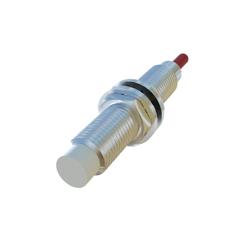
Signal Line Voltage Behavior in Operation
When a proximity sensor detects a target, its internal solid-state switch changes state. For a standard 24V DC PNP sensor, the signal line voltage, which was near 0V (or a leakage voltage) in the off-state, will rise to approximately the supply voltage (minus a small voltage drop, typically 0.5-2V) when active. Conversely, an NPN sensor's signal line will be pulled close to 0V (ground) when active. It is crucial to note that this voltage is presented to the load (e.g., a PLC input). The actual measured voltage can vary based on line resistance, electrical noise, and the input impedance of the receiving device. A "healthy" signal voltage must be within a defined threshold for the control system to reliably register a logic HIGH or LOW state.
Factors Influencing Signal Voltage Integrity
Several practical factors can degrade or alter the expected voltage on the signal line. Long cable runs introduce resistance and capacitance, potentially leading to voltage drop and signal delay, especially with high leakage currents. Electrical noise from motors, variable frequency drives (VFDs), or welding equipment can induce transient voltages on the signal line, causing false triggering. Proper shielding, twisted-pair cables, and routing away from power lines are mandatory countermeasures. Load current is another key factor; each sensor has a maximum switching capacity. Exceeding this by connecting too many devices in parallel can cause the output voltage to sag below the required logic level, leading to failure.
Wiring Configurations and Voltage Measurement
Correct wiring is paramount for establishing the proper signal voltage. A typical three-wire sensor has brown (V+), blue (V- or ground), and black (signal output) wires. Miswiring can result in no voltage, incorrect voltage polarity, or even permanent damage. Diagnosing signal line issues requires systematic voltage measurement with a digital multimeter. Measurements should be taken between the sensor's black signal wire and the blue wire (common) with the sensor activated and deactivated, comparing readings to the datasheet specifications. Checking for the correct supply voltage between brown and blue is always the first step. Understanding if the control input is designed for a sourcing (PNP) or sinking (NPN) signal is essential before connecting the sensor.
Troubleshooting Voltage-Related Issues
Common symptoms of signal voltage problems include erratic PLC input status, failure to detect objects, or sensors that seem "stuck on." A low output voltage under load may indicate a failing sensor output transistor or an overloaded circuit. A signal voltage that never reaches zero might point to excessive leakage current or a wiring short. Using an oscilloscope can reveal noise superimposed on the DC signal. Solutions often involve verifying the load compatibility, ensuring the power supply is stable and adequately sized, inspecting cables and connections for damage, and finally, replacing the sensor if its output characteristics are out of specification. Always consult the manufacturer's datasheet for precise voltage thresholds and timing diagrams.