Understanding Photoelectric Sensor Fundamentals
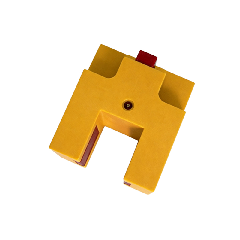
Photoelectric sensors are indispensable components in modern industrial automation, particularly on conveyor belt systems. They operate by emitting a beam of light, typically from an LED, and detecting changes in the received light signal. The three primary types are through-beam, retro-reflective, and diffuse reflective sensors. Through-beam sensors consist of separate emitter and receiver units, offering the longest sensing range and highest reliability. Retro-reflective models use a single housing with both emitter and receiver, relying on a reflector to bounce the light back. Diffuse sensors detect light reflected directly from the target object itself. Selecting the correct type is the foundational step before any installation process begins, as it directly impacts performance in detecting presence, position, counting, or sorting on a moving conveyor.
Pre-Installation Planning and Site Assessment
Thorough planning is critical for a successful installation. Begin by conducting a detailed site assessment of the conveyor system. Identify the precise location where the sensor is needed—is it for detecting product presence at a specific point, triggering a diverter, or ensuring proper spacing? Consider the environmental factors: potential exposure to dust, moisture, vibration, or extreme temperatures will dictate the required ingress protection (IP) rating of the sensor housing. Analyze the target objects: their size, color, material, and surface finish (shiny or matte) can affect light absorption and reflection. Furthermore, assess the available mounting space and the conveyor's structure to determine the most feasible and secure mounting method. This stage should also include verifying power supply requirements and ensuring compatibility with the conveyor's control system, typically a PLC.
Selecting the Optimal Mounting Position and Hardware
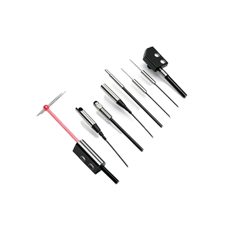
The mounting position is paramount for reliable detection. For through-beam sensors, ensure perfect alignment between the emitter and receiver across the conveyor's width. Even minor misalignment can cause false signals or failure to detect. Mount them on stable, rigid brackets to prevent movement from conveyor vibration. For side-mounted sensors detecting objects passing by, the height and angle must be calibrated to the object's profile. Avoid mounting near points of product transfer where dust or debris may be airborne. Use high-quality, corrosion-resistant mounting hardware—brackets, clamps, and bolts—designed for industrial environments. Adjustable mounting brackets are highly recommended as they allow for fine-tuning during setup and future recalibration. The goal is to create a rigid, vibration-resistant setup that maintains precise optical alignment under continuous operation.
Wiring and Electrical Connection Procedures
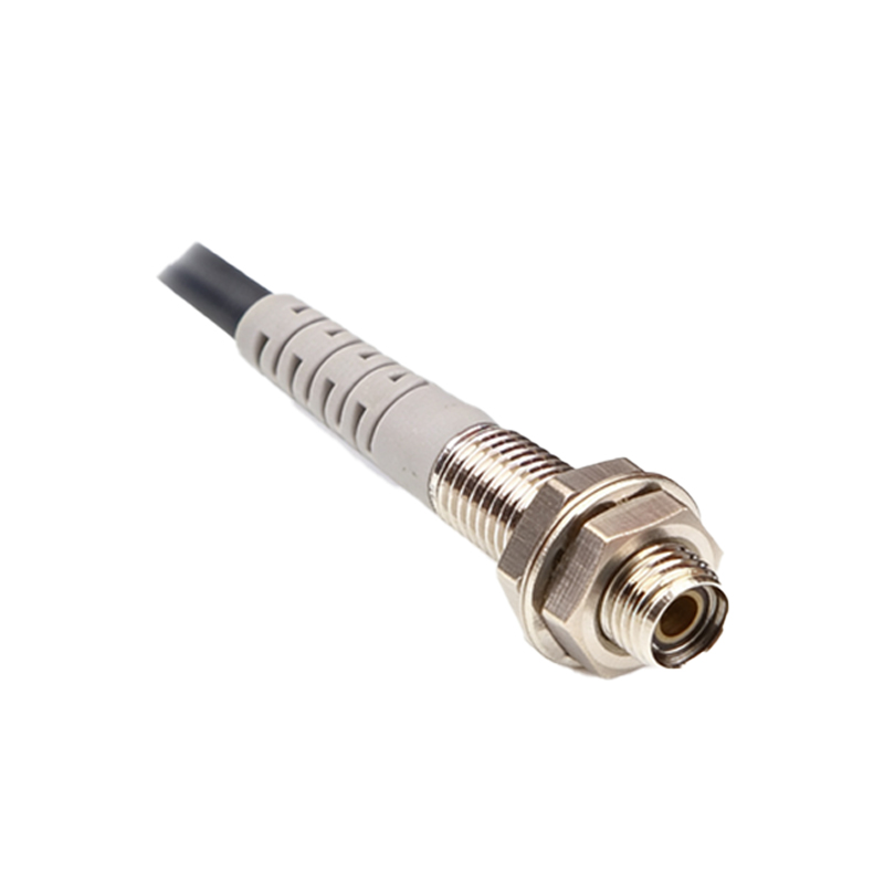
Correct wiring is essential for both functionality and safety. Always disconnect power to the conveyor control circuit before beginning any electrical work. Follow the sensor manufacturer's wiring diagram meticulously. Most photoelectric sensors have three or four wires: typically brown for DC positive (+V), blue for DC common (0V), black for the output signal (often NPN or PNP), and sometimes a white wire for additional functions like output inversion. Use shielded cable for the run back to the PLC or controller to protect against electromagnetic interference (EMI) from motors or drives. Secure cable connections with appropriate wire ferrules and ensure terminals are tightly fastened. Implement proper strain relief for the sensor cable at the connection point to prevent wire breakage from constant movement or tugging. Finally, verify that the electrical characteristics (voltage, current) match the sensor's specifications and the PLC input module's requirements.
Configuration, Alignment, and Sensitivity Adjustment
After secure mounting and wiring, power on the system for configuration. The initial step is precise optical alignment. For through-beam sensors, this often involves using the sensor's built-in alignment indicator (usually an LED that changes color or brightness) to achieve the strongest possible signal. Many modern sensors feature a teach-in function or potentiometers for adjusting sensitivity. Set the sensitivity threshold high enough to reliably detect the target object but low enough to ignore background interference, such as dust on the lens or minor reflective surfaces. Test the setup by running actual or representative products down the conveyor at normal operational speed. Observe the sensor's response LED and monitor the input indicator on the PLC to ensure consistent, accurate detection with no missed or false triggers.
Implementing Protective Measures and Shielding
To ensure long-term reliability, implement protective measures. Install physical guards or barriers if the sensor is in a location prone to impact from products, maintenance tools, or personnel. For sensors in dusty or dirty environments, consider models with built-in air purge connections to keep the lens clean, or establish a regular lens cleaning schedule. Use optical filters or polarizing lenses if dealing with highly reflective targets or background interference from ambient light. In areas with strong ambient light (sunlight or high-intensity factory lighting), select sensors with modulated LED light and corresponding synchronous detection to avoid interference. Additionally, ensure the sensor's operating temperature range is not exceeded by the local environment, as heat from nearby machinery or direct sunlight can affect performance.
Systematic Testing, Documentation, and Maintenance
Conduct comprehensive testing under all expected operating conditions. This includes running the conveyor at minimum and maximum speeds, testing with all product variants, and simulating potential fault conditions like overlapping items or jams. Document the installation thoroughly: note the sensor model, serial number, installed location, wiring diagram reference, sensitivity setting, and alignment details. This documentation is invaluable for future troubleshooting or replacement. Establish a preventive maintenance routine. Periodically check the sensor for physical damage, lens cleanliness, and mounting stability. Re-verify alignment and sensitivity at scheduled intervals, as vibration can slowly shift components over time. A well-planned installation, coupled with diligent maintenance, maximizes sensor uptime and contributes to the overall efficiency and reliability of the conveyor system.