Understanding Proximity Sensor Fundamentals
Proximity sensors are non-contact electronic devices designed to detect the presence or absence of an object within their sensing field. Widely used in industrial automation, they offer high reliability and long operational life. The core principle involves generating an electromagnetic field or beam and monitoring changes caused by a target object. There are three primary types: inductive (for metallic objects), capacitive (for both metallic and non-metallic objects), and photoelectric (using light beams). Each type has specific wiring requirements and considerations. Understanding the basic sensor specifications, such as sensing distance, output type (NPN or PNP), and voltage rating, is the critical first step before any physical connection is made. Incorrect identification can lead to malfunction or damage to the sensor or the connected controller.
Essential Components and Wiring Tools
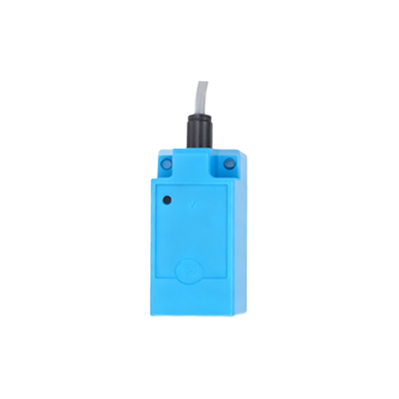
Before commencing the wiring process, gather all necessary components. This typically includes the proximity sensor itself, a suitable DC power supply (commonly 10-30V DC), the load device (such as a PLC input module, relay, or indicator lamp), and the connecting cables. The essential tools are wire strippers, crimping tools, screwdrivers, and a multimeter for verification. Always refer to the sensor's datasheet for its specific pin configuration diagram. Most standard 3-wire sensors have three distinct leads: brown (or red) for the positive supply voltage (+V), blue (or black) for the common negative (0V), and black (or white) for the output signal. A 2-wire sensor simplifies this but requires careful consideration of the load compatibility and leakage current.
Decoding NPN and PNP Output Configurations
This is a crucial distinction in sensor wiring. The terms NPN and PNP refer to the type of transistor switch used in the sensor's output circuit. An NPN sensor, also known as a sinking sensor, switches the negative (0V) line to the load. In a typical NPN wiring diagram, the load is connected between the sensor's output wire and the positive supply (+V). When activated, the sensor connects the load to 0V, completing the circuit. Conversely, a PNP sensor, or a sourcing sensor, switches the positive voltage line. Here, the load is connected between the sensor's output and the common negative (0V). The sensor provides the +V to the load when triggered. Matching the sensor's output type (NPN/PNP) with the controller's input type is absolutely mandatory for proper operation.
Step-by-Step Inductive Sensor Wiring Example
Let's examine a practical wiring example for a common 3-wire DC inductive proximity sensor with a PNP (sourcing) output, intended to connect to a PLC digital input. First, ensure the power is OFF. Connect the blue wire from the sensor to the DC power supply's negative terminal (0V). Connect the brown wire from the sensor to the DC power supply's positive terminal (+24V). The sensor now has power. Next, take the black (output) wire from the sensor and connect it to one terminal of your load—in this case, the specific PLC input point (e.g., I0.0). Finally, connect the other side of that PLC input point to the common negative (0V) of the power supply. This creates a complete path: +24V -> sensor (internal switch) -> PLC input -> 0V. When a metal object enters the sensing range, the internal PNP transistor activates, sourcing +24V to the PLC input, signaling a TRUE state.
Wiring a 2-Wire AC Proximity Sensor
Two-wire sensors are simpler to connect as they are wired in series with the load and the power supply, similar to a mechanical switch. They are commonly used in AC circuits. For an AC sensor, connect one wire directly to the AC line voltage (e.g., L1 120VAC). Connect the other sensor wire to one terminal of the load (like a relay coil). Finally, connect the remaining terminal of the load to the neutral line (N) of the AC supply. It is vital to note that 2-wire sensors have a residual leakage current (a few mA) even when in the OFF state. The connected load must have a minimum current draw (hold current) greater than this leakage value to ensure it turns off reliably. Always check the sensor's datasheet for these critical parameters.
Critical Safety and Troubleshooting Practices
Safety is paramount. Always lock out and tag out power sources before wiring. Use fuses or circuit breakers rated for the sensor circuit for protection. After wiring, double-check all connections