Introduction to Proximity Switch Symbols
Proximity switch sensors are essential components in industrial automation and electrical control systems, detecting the presence or absence of objects without physical contact. In electrical schematics, these sensors are represented by standardized symbols that convey their type, function, and electrical characteristics. Understanding these symbols is crucial for engineers, technicians, and designers to interpret circuit diagrams accurately. The symbols vary based on the sensor technology—such as inductive, capacitive, or ultrasonic—and their output configurations, including normally open (NO) or normally closed (NC) contacts. This article delves into the common symbol representations, their meanings, and practical applications in circuit design.
Standard Symbol Conventions and Basics
Electrical schematics follow international standards, primarily set by organizations like the International Electrotechnical Commission (IEC) and the Institute of Electrical and Electronics Engineers (IEEE). For proximity switches, symbols typically consist of a basic switch representation combined with additional markings to indicate sensing technology. A general proximity switch symbol resembles a standard switch with a diamond shape or a circle attached, denoting non-contact operation. For example, an inductive proximity sensor might include a coil-like element, while a capacitive one could show parallel plates. These symbols are often accompanied by labels specifying parameters like sensing distance, voltage ratings, and output type (e.g., PNP or NPN for solid-state outputs). Consistency in symbol usage ensures clear communication across global engineering teams.
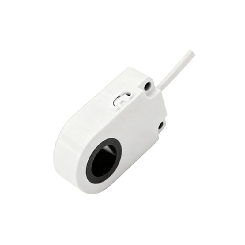
Inductive Proximity Sensor Symbols
Inductive proximity sensors detect metallic objects using electromagnetic fields. In schematics, their symbol typically features a switch graphic with a coil or inductor symbol adjacent to it, indicating the inductive principle. The IEC standard uses a rectangle with a diagonal line and a coil icon, while IEEE may depict it as a circle with an "L" inside. Outputs are represented by arrows or lines: a NO contact is shown as a break in the line that closes upon detection, whereas an NC contact appears as a closed line that opens. Additional annotations might include "DC" for direct current operation or specific codes like "3-wire" for wiring configurations. These symbols help in planning circuits for machinery where metal detection is critical, such as in conveyor systems or robotic arms.
Capacitive Proximity Sensor Symbols
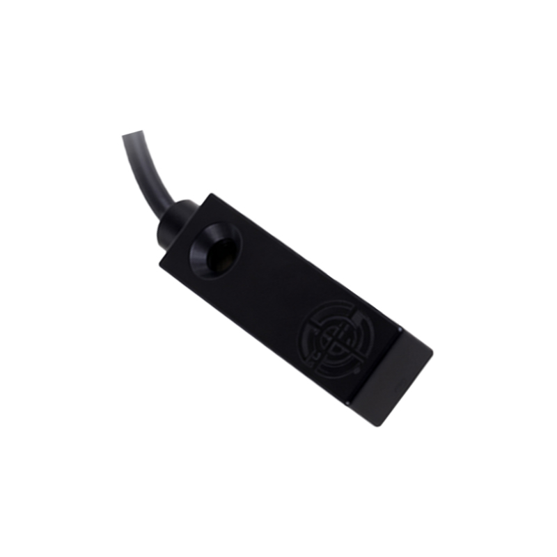
Capacitive proximity sensors sense both metallic and non-metallic materials by measuring changes in capacitance. Their schematic symbols often incorporate two parallel lines or plates near the switch element, symbolizing the capacitive plates. According to IEC norms, this might be represented as a rectangle with parallel lines inside, while other standards use a circle with a "C" label. The output symbols mirror those of inductive sensors but may include notes for sensitivity adjustments. In applications like liquid level detection or plastic part handling, these symbols guide engineers in integrating sensors that require precise material differentiation, ensuring proper circuit connections for power and signal outputs.
Ultrasonic and Optical Proximity Sensor Symbols
Ultrasonic proximity sensors use sound waves for detection and are symbolized by wavy lines or sound wave icons adjacent to the switch graphic. Optical sensors, including infrared types, often show a light beam or diode symbol. For instance, an ultrasonic sensor might have a symbol with a transmitter and receiver depicted as concentric circles, while an optical sensor could include an LED-like shape. These symbols highlight the non-contact nature and specific sensing medium, aiding in circuit designs for distance measurement or object counting in automated systems. Engineers must note output types, such as analog or digital signals, which are indicated by additional markings like sine waves for analog outputs.
Output Configuration Symbols and Wiring
Proximity switch symbols also detail output configurations, which are vital for circuit functionality. Common outputs include relay contacts, transistor-based (PNP/NPN), and analog outputs. Relay outputs are shown with standard switch symbols, while transistor outputs use arrows pointing inward (PNP) or outward (NPN) to indicate current flow. In schematics, a PNP sensor symbol might include a positive voltage marker, whereas an NPN shows a ground connection. Wiring diagrams often accompany these symbols, depicting power supply lines (e.g., +24V DC) and load connections. Proper interpretation prevents errors in control logic, especially in programmable logic controller (PLC) systems where sensor inputs trigger automated responses.
Practical Applications and Schematic Examples
In real-world applications, proximity switch symbols appear in ladder diagrams, wiring plans, and control panel layouts. For example, a manufacturing line schematic might use inductive sensor symbols to show part detection points, with NO contacts controlling motor starters. Another case could involve capacitive symbols in packaging machines to sense material presence. Engineers use these symbols to