Introduction to Proximity Sensing Technology
Proximity sensors are indispensable components in modern industrial automation, providing non-contact detection of objects within a defined range. Unlike mechanical limit switches, these electronic devices operate without physical contact, thereby eliminating wear and tear and enabling high-speed, reliable operation. The core principle behind many proximity sensors, particularly inductive and capacitive types, is the use of an oscillation circuit. This circuit generates a high-frequency electromagnetic field at the active face of the sensor. The presence of a target object within this field causes a detectable change in the circuit's oscillatory behavior, which is then processed to trigger an output signal. This technology forms the backbone of countless applications, from assembly line object counting and position verification to safety interlocking and robotic guidance systems. The reliability and longevity of these sensors are directly tied to the stability and design of their internal oscillation circuitry.
The Heart of Detection: The Oscillator Circuit
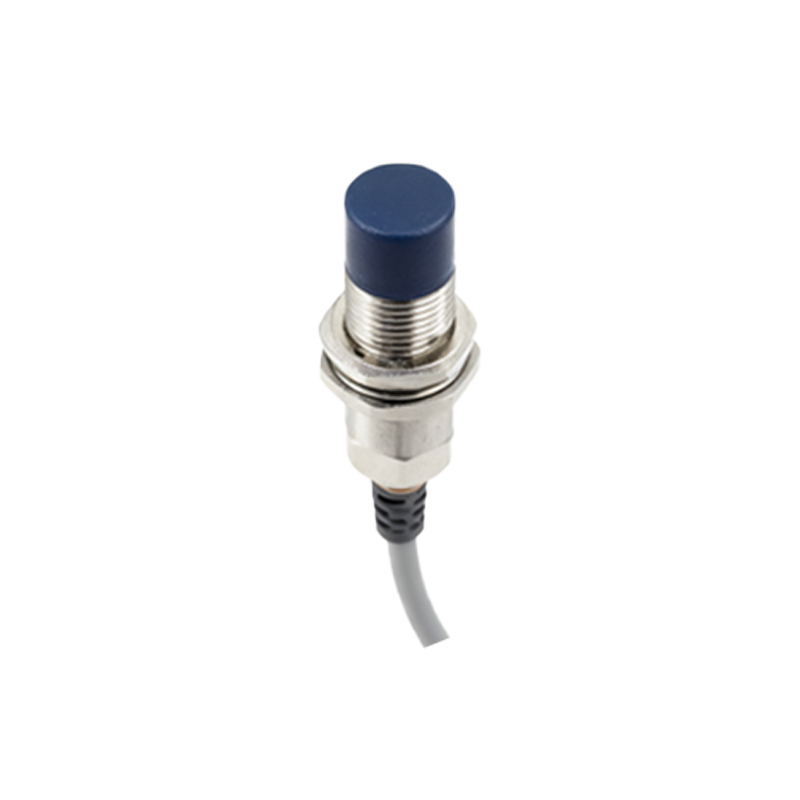
At the core of a typical inductive proximity sensor lies a tuned LC oscillator circuit. This circuit consists of a coil (L), which also acts as the sensor's sensing face, and a capacitor (C) arranged in a parallel configuration. When powered, this LC tank circuit is excited to oscillate at its resonant frequency, typically in the range of 100 kHz to 1 MHz. This oscillation sustains a constant alternating magnetic field radiating from the coil. The design ensures the oscillator runs in a stable, high-amplitude state when no target is present. The oscillation amplitude is continuously monitored by a subsequent evaluation circuit. The precise values of L and C determine the resonant frequency, which is a critical parameter for the sensor's sensitivity and immunity to electrical noise. Advanced designs may incorporate crystal oscillators or RC circuits for specific applications, but the LC tank remains the industry standard for its simplicity and effectiveness in generating the required electromagnetic field.
Target Interaction and Damping Phenomenon
When a conductive metallic target enters the oscillating magnetic field, electromagnetic induction principles come into play. Eddy currents are induced on the surface of the target object. These circulating currents create their own magnetic field, which opposes the original field generated by the sensor's coil, following Lenz's Law. This opposition results in an energy loss from the oscillator circuit, a phenomenon known as "damping." The effective impedance of the coil increases, and the amplitude of the oscillation begins to decrease. The degree of damping is proportional to the target's conductivity, permeability, size, and distance from the sensor face. Ferrous metals, with high permeability, cause the most significant damping effect. This reduction in amplitude is the primary detectable event that signals the presence of a target.
Signal Evaluation and Output Switching
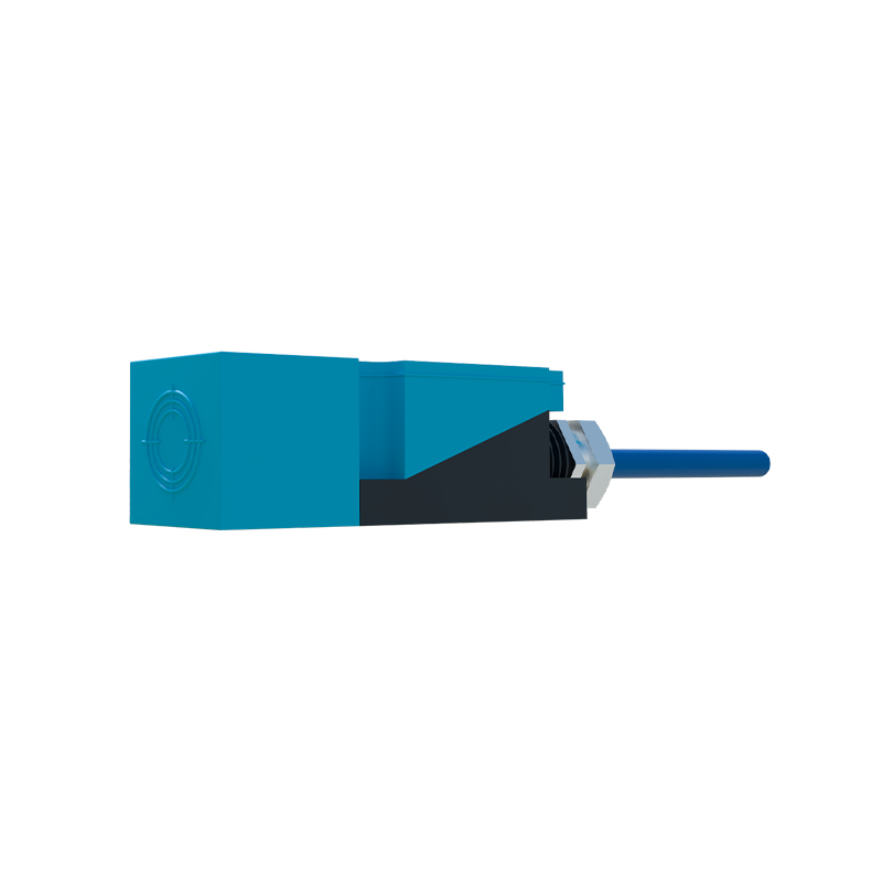
The damped oscillation signal is fed into an amplitude detection or threshold circuit. This circuit continuously compares the oscillation amplitude against a predefined reference level. When the amplitude falls below this threshold due to target-induced damping, the evaluation circuit recognizes this as a "target present" condition. It then triggers a solid-state output switch, typically a transistor, to change state. For a normally open (NO) sensor, the output turns ON (conducts). This state change is what interfaces with the programmable logic controller (PLC), relay, or other control system. Hysteresis is built into the evaluation circuit to prevent output chatter when a target is at the exact sensing point; the switch-off point (target moving away) is set at a slightly lower damping level than the switch-on point. This ensures clean, definitive switching even with vibrating targets or minor electrical noise.
Key Performance Parameters and Circuit Design
The performance of a proximity sensor is defined by parameters intrinsically linked to its oscillator design. The nominal sensing distance (Sn) is the rated operating distance for a standard target. Factors like the coil's size, number of windings, and core material directly influence this range. Frequency of operation, or switching frequency, dictates how quickly the sensor can detect successive objects. A stable, quickly responding oscillator circuit is essential for high-speed applications. Temperature stability is another critical concern; quality sensors use components with low temperature coefficients in the LC circuit and compensated evaluation electronics to maintain consistent sensing performance across industrial temperature ranges. Furthermore, electromagnetic compatibility (EMC) is crucial. The oscillator circuit must be shielded and designed to neither emit excessive interference nor be susceptible to it from nearby drives or communication systems.
Applications and Selection Criteria
Understanding the interplay between the oscillation circuit and sensing mechanism guides proper sensor selection. Inductive sensors, with their LC oscillators, are exclusively for detecting metals. Capacitive sensors use a similar oscillator principle but respond to changes in capacitance caused by any material, making them suitable for liquids, plastics, or wood. In harsh environments, sensors with robust, potted oscillator