Introduction to Proximity Switch Sensors in Spring Wire Systems
Proximity switch sensors are critical components in industrial automation, particularly in spring wire applications where precise detection of metallic objects is required. These sensors operate without physical contact, using electromagnetic fields to identify the presence of targets, making them ideal for environments with high vibration or mechanical wear. In spring wire systems, they ensure accurate positioning and control, enhancing efficiency and safety. Understanding the wiring diagram is essential for proper installation and functionality, as incorrect connections can lead to sensor failure or system malfunctions. This article provides a detailed guide on wiring proximity switch sensors, tailored for spring wire setups, to help engineers achieve reliable performance.
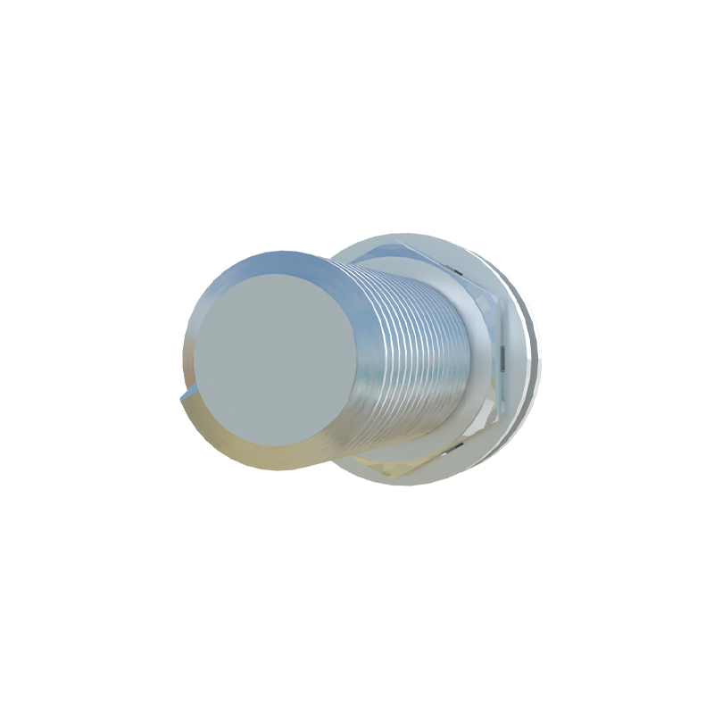
Key Components of a Proximity Switch Sensor
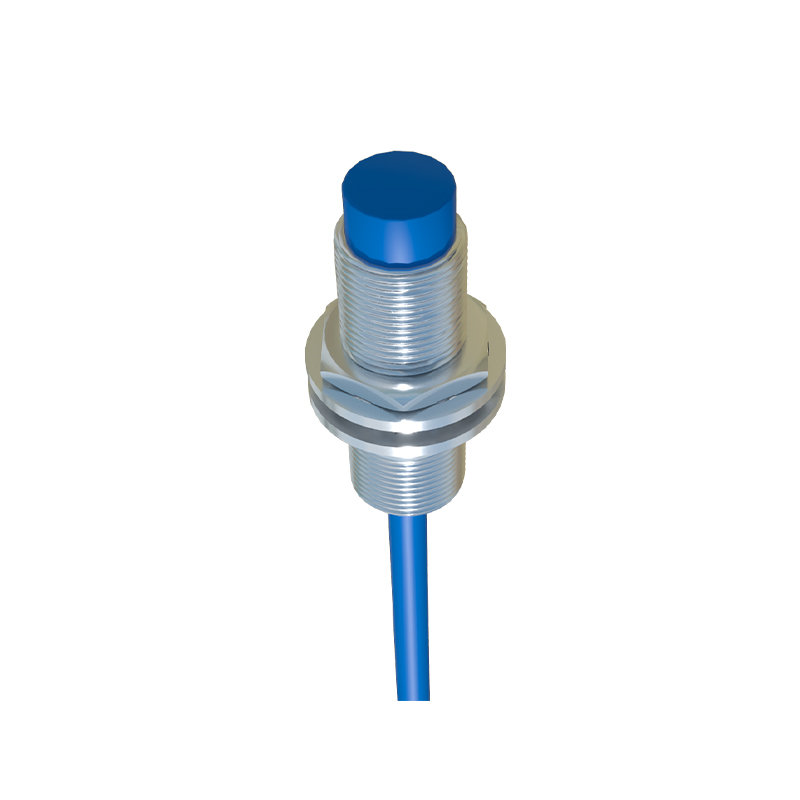
A typical proximity switch sensor consists of several key parts: the sensing head, which generates the electromagnetic field; the housing, often made of durable materials like stainless steel for spring wire environments; and the electrical connections, including power supply wires, output wires, and ground wires. The sensor may be classified as inductive, capacitive, or magnetic, with inductive types being most common for metallic spring wire detection. It typically has three or four wires: brown for positive voltage, blue for negative or ground, black for output signal, and sometimes white for additional functions like diagnostics. Familiarity with these components ensures correct interpretation of wiring diagrams and prevents errors during installation.
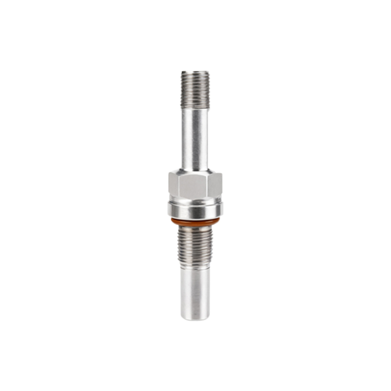
Wiring Diagram Overview for Spring Wire Applications
The wiring diagram for a proximity switch sensor in spring wire systems outlines how to connect the sensor to a control unit, such as a PLC or relay. For a standard three-wire DC sensor, the brown wire connects to the positive terminal of the power supply (usually 10-30V DC), the blue wire to the negative terminal, and the black wire to the input of the control device. In spring wire setups, it's crucial to ensure proper grounding to avoid interference from electrical noise, which can affect sensor accuracy. Diagrams often include symbols for power sources, loads, and protective devices like fuses. Following the manufacturer's diagram precisely is vital, as variations exist between sensor models and brands.
Step-by-Step Wiring Instructions
Begin by disconnecting all power sources to prevent electrical hazards. Identify the sensor wires based on color codes: brown for positive, blue for negative, and black for output. Connect the brown wire to the positive supply terminal and the blue wire to the negative terminal, ensuring tight connections to avoid loose contacts. For the output, link the black wire to the control input, such as a PLC digital input module. In spring wire applications, use shielded cables to minimize electromagnetic interference from nearby machinery. Test the connections with a multimeter to verify voltage levels and continuity before powering up the system. Always refer to the specific sensor datasheet for any unique requirements.
Common Wiring Mistakes and Troubleshooting Tips
Common errors in wiring proximity switch sensors include reversed polarity, incorrect voltage supply, and poor grounding. Reversing the brown and blue wires can damage the sensor, so double-check connections. Ensure the power supply matches the sensor's rated voltage (e.g., 12V DC or 24V DC) to prevent overheating. In spring wire systems, inadequate grounding may cause false triggers; use a dedicated ground point and avoid sharing grounds with high-power equipment. If the sensor fails to detect targets, check for obstructions, adjust the sensing distance, or inspect for wire damage. Regular maintenance, such as cleaning the sensing head, can also improve longevity and performance.
Safety Considerations and Best Practices
Safety is paramount when wiring proximity switch sensors in industrial settings. Always follow lockout-tagout procedures to isolate energy sources during installation. Use appropriate personal protective equipment, such as gloves and safety glasses, to prevent injuries. For spring wire applications, ensure the sensor is mounted securely to withstand vibrations and environmental factors like moisture or dust. Implement overcurrent protection with fuses or circuit breakers to safeguard against short circuits. Document the wiring setup and label all connections for future reference, facilitating easier troubleshooting and upgrades. Adhering to industry standards, such as IEC or NEC guidelines, ensures compliance and reliability.
Conclusion and Future Trends
Proper wiring of proximity switch sensors is essential for optimal performance in spring wire systems, contributing to enhanced automation and reduced downtime. As technology advances, sensors are becoming more integrated with IoT and smart factory systems, offering features like wireless connectivity and self-diagnostics. Engineers should stay updated on these trends to leverage improved efficiency and data analytics. By mastering wiring diagrams and following best practices, professionals can ensure robust and safe operations in diverse industrial applications. For further guidance, consult technical manuals or attend training sessions to