Introduction to Snap-in Photoelectric Sensors
Snap-in photoelectric sensors are widely used in industrial automation for object detection, positioning, and counting. These sensors operate by emitting a light beam and detecting changes in the received light intensity. The "snap-in" design refers to their easy installation mechanism, which allows quick mounting into panels or enclosures without additional hardware. This feature makes them highly popular in manufacturing lines, packaging systems, and conveyor belt applications. Their robust construction ensures reliable performance in harsh environments, including areas with dust, moisture, or vibration. Understanding the working principle of these sensors is essential for optimizing their use in various automation tasks.
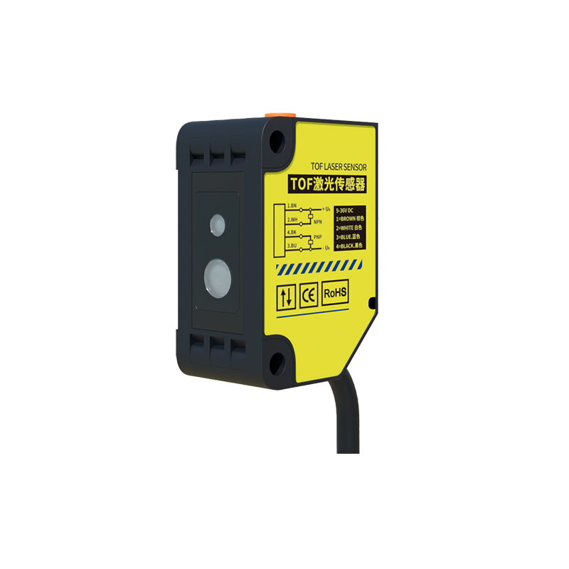
Basic Components and Structure
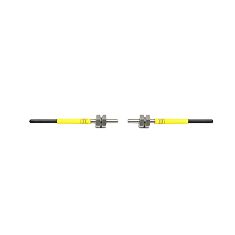
A snap-in photoelectric sensor consists of several key components: a light emitter (typically an LED), a light receiver (such as a phototransistor or photodiode), a signal processing circuit, and a housing with a snap-in mounting mechanism. The emitter generates a modulated light beam, often in the infrared or visible spectrum, to avoid interference from ambient light. The receiver detects the light beam and converts it into an electrical signal. The housing is designed with a spring-loaded clip or latch that allows the sensor to be securely snapped into a pre-cut hole, ensuring proper alignment and stability. This compact design minimizes installation time and maintenance efforts.
Working Principle Diagram Overview
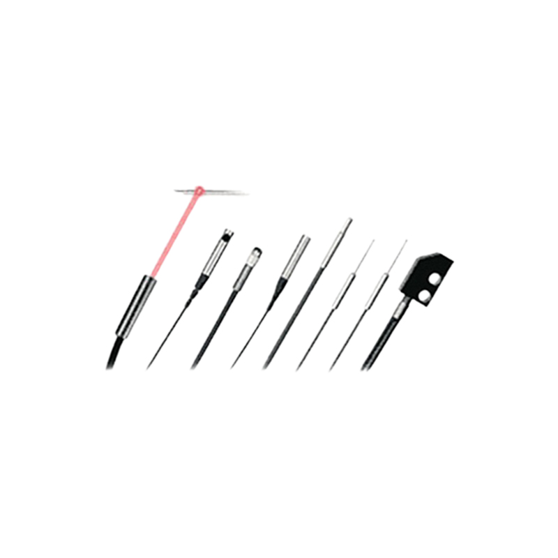
The working principle of a snap-in photoelectric sensor can be illustrated through a diagram showing the light path and detection process. In the diagram, the emitter sends a focused light beam toward a target object. When the object interrupts or reflects the beam (depending on the sensor type), the receiver detects the change in light intensity. The signal processing circuit then amplifies and converts this change into a digital output, such as a switch signal. Diagrams often include labels for the emitter, receiver, optical axis, and detection zone, helping users visualize how the sensor interacts with objects. This visual aid is crucial for troubleshooting and selecting the right sensor for specific applications.
Types of Detection Methods
Snap-in photoelectric sensors employ different detection methods, each suited to particular scenarios. The through-beam (or opposed) type uses separate emitter and receiver units placed opposite each other; detection occurs when an object blocks the light beam. The retro-reflective type has both emitter and receiver in one housing, relying on a reflector to bounce the light back; objects are detected when they break the reflected beam. The diffuse (or proximity) type detects objects by measuring the light reflected directly from the target. Diagrams for each method highlight the unique light paths and alignment requirements, aiding in proper installation and operation.
Signal Processing and Output
Once the receiver detects light changes, the internal signal processing circuit plays a vital role. It filters out noise, such as ambient light interference, using modulation techniques. The circuit then compares the received signal with a threshold to determine the presence or absence of an object. Output options include digital signals (e.g., NPN/PNP transistors) or analog signals for distance measurement. In snap-in designs, the output is often integrated into a connector or cable for easy wiring. Diagrams may show waveform representations of the signal processing stages, emphasizing how raw light data is transformed into reliable detection signals for industrial controllers.
Installation and Alignment Tips
Proper installation is critical for optimal sensor performance. The snap-in mechanism simplifies mounting, but alignment must be precise to ensure accurate detection. Diagrams often include guidelines for hole dimensions, sensor orientation, and clearance distances. For through-beam sensors, the emitter and receiver must be directly aligned; retro-reflective sensors require correct positioning relative to reflectors. Environmental factors like dirt or strong light sources can affect performance, so diagrams may illustrate protective measures, such as using shrouds or filters. Regular maintenance, including lens cleaning and output testing, helps sustain long-term reliability.
Applications in Industrial Automation
Snap-in photoelectric sensors are versatile tools in automation systems. Common applications include object detection on assembly lines, bottle counting in packaging, and edge guiding in printing machines. Their quick installation makes them ideal for high-mix production environments where sensors need frequent replacement or adjustment. Diagrams can showcase real-world setups, such as sensors monitoring conveyor belts or detecting misaligned parts. By understanding the principle diagrams, engineers can customize sensor placements to improve efficiency, reduce downtime, and enhance safety in automated processes.
Advantages and Limitations
The snap-in design offers significant advantages, including reduced installation time, cost savings on mounting hardware, and flexibility in panel integration. These sensors are generally resistant to shock and vibration due to their secure fit. However, limitations exist, such as detection range constraints compared to larger sensors, and potential sensitivity issues in highly reflective environments. Diagrams help illustrate these aspects by comparing snap-in sensors with other types, highlighting trade-offs in size, range, and environmental tolerance. Selecting the right sensor involves balancing these factors based on application needs.
Future Trends and Innovations
Advancements in snap-in photoelectric sensor technology focus on miniaturization, enhanced connectivity, and smarter features. Future diagrams may include integrated IoT capabilities for real-time monitoring or AI-driven adjustment of detection parameters. Innovations in light sources, such as laser LEDs, could extend detection ranges and accuracy. As industries adopt more flexible automation, snap-in sensors are evolving to support easier configuration and diagnostics via digital interfaces. Understanding current principle diagrams prepares users for these trends, enabling seamless integration into next-generation industrial systems.