Introduction to Proximity Switch Sensor PCBs
Proximity switch sensor printed circuit boards (PCBs) are fundamental components in modern industrial automation systems. These specialized PCBs integrate sensing elements, signal conditioning circuits, and output interfaces to detect the presence or absence of objects without physical contact. The core functionality relies on electromagnetic, capacitive, or inductive principles, where the PCB layout and component selection are critical for performance. A well-designed proximity sensor PCB ensures reliable operation in harsh industrial environments characterized by dust, moisture, vibration, and electromagnetic interference. The design process involves careful consideration of factors such as sensing range, response time, power consumption, and output type (e.g., NPN, PNP, or analog). Engineers must select appropriate materials, like FR-4 or polyimide for the substrate, and incorporate protective coatings to enhance durability. The miniaturization trend has also led to the development of compact, surface-mount technology (SMT) based PCBs, enabling integration into space-constrained applications.
Key Design Considerations and Circuit Architecture
The circuit architecture of a proximity sensor PCB typically comprises an oscillator, demodulator, amplifier, and output stage. For inductive proximity sensors, a coil etched onto the PCB forms part of an LC oscillator circuit. When a metallic object enters the sensing field, eddy currents are induced, causing a change in oscillation amplitude or frequency. This change is detected, demodulated, and amplified to trigger a solid-state switch on the output stage. Capacitive sensors use a similar approach but with electrode plates to detect changes in capacitance caused by both conductive and non-conductive materials. Key design considerations include noise immunity, achieved through proper grounding, shielding, and filtering techniques. Trace routing must minimize parasitic capacitance and inductance. Power supply regulation is vital to maintain stable operation against voltage fluctuations. Thermal management is also crucial, especially for high-frequency or high-current designs, to prevent component degradation and ensure long-term reliability.
Material Selection and Manufacturing Processes
Material selection for proximity sensor PCBs directly impacts their performance and longevity. Standard FR-4 laminate is common for general-purpose applications due to its good electrical insulation and mechanical strength. For high-frequency or high-temperature environments, materials like Rogers or ceramic-filled PTFE composites may be used to ensure stable dielectric properties. The copper thickness for traces and the coil (in inductive sensors) affects current-carrying capacity and sensing sensitivity. Manufacturing processes involve precise etching to create fine-pitch coils and circuit patterns. Solder mask application protects copper traces from oxidation and short circuits, while silkscreen aids in component placement and identification. For extreme environments, conformal coatings such as acrylic, silicone, or polyurethane are applied to protect against moisture, chemicals, and contaminants. Automated optical inspection (AOI) and functional testing are essential quality control steps to verify electrical characteristics and sensing performance before deployment.
Integration and Application in Industrial Systems
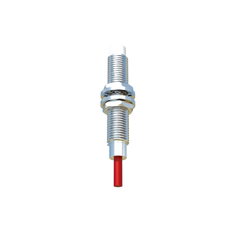
Proximity sensor PCBs are integrated into various housings, typically made of stainless steel, brass, or PBT plastic, to form complete sensor units. These units are then deployed across numerous industrial applications. In automated assembly lines, they detect part presence, count objects, or verify positioning. On packaging machinery, they monitor fill levels or control product flow. In robotics, they provide end-of-arm tooling feedback for precise object handling. Safety systems use them as non-contact limit switches to prevent machine collisions. The output signals from these PCBs interface directly with programmable logic controllers (PLCs), motor drives, or other control systems. Network-enabled sensors with integrated IO-Link or Ethernet connectivity are becoming increasingly prevalent, allowing for remote configuration, diagnostics, and data exchange, facilitating predictive maintenance and Industry 4.0 initiatives.
Future Trends and Technological Advancements
The future of proximity switch sensor PCBs is shaped by advancements in miniaturization, intelligence, and robustness. The integration of microcontrollers (MCUs) directly onto the sensor PCB enables smart features like self-diagnostics, temperature compensation, and adaptive sensing thresholds. Developments in embedded antenna designs are enhancing the capabilities of high-frequency RFID-based proximity sensors. There is also a growing emphasis on energy-efficient designs for battery-operated or energy-harvesting applications in wireless sensor networks. Furthermore, the use of advanced simulation software allows for optimized electromagnetic field modeling and thermal analysis during the design phase, reducing prototyping cycles. As industrial IoT expands, sensor PCBs will increasingly incorporate secure communication protocols and edge-computing capabilities, transforming simple detection devices into intelligent nodes within larger data-driven ecosystems.