Understanding 2-Wire DC Proximity Sensor Fundamentals
A 2-wire DC proximity sensor is a widely used component in industrial automation for detecting the presence or absence of metallic objects without physical contact. Unlike their 3-wire or 4-wire counterparts, these sensors integrate the switching element directly into the power line, simplifying installation but requiring careful consideration of electrical characteristics. The fundamental principle involves the sensor drawing a small leakage current (often termed standby current) when in the off state and a higher operational current when activated. This design means the sensor itself acts as a variable resistor or solid-state switch within the DC circuit. Common operating voltages range from 10 to 30 VDC, with the sensor's output being either normally open (NO) or normally closed (NC). Understanding that the load (e.g., a PLC input, relay coil, or indicator lamp) is connected in series with the sensor is the first critical step toward correct wiring and reliable operation.
Key Electrical Parameters and Selection Criteria
Before proceeding with wiring, verifying the sensor's specifications against the application requirements is paramount. The datasheet must be consulted for key parameters: the operating voltage range, rated switching current, leakage current, and voltage drop. The leakage current, typically between 1 to 2 mA, is the current that flows through the sensor and the connected load even when the sensor is in the off state. This current must be low enough not to inadvertently activate the connected device—a phenomenon known as phantom switching. Conversely, the voltage drop across the sensor when active (usually 1.5 to 3 volts) reduces the voltage available to the load. Therefore, the power supply voltage must be sufficiently high to compensate for this drop and ensure the load receives adequate voltage. Selecting a sensor with an appropriate IP rating for the environmental conditions (dust, moisture, etc.) and the correct sensing distance for the target object is equally crucial.
Standard Wiring Configuration and Circuit Diagram
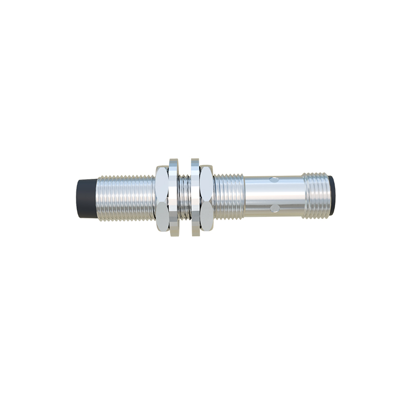
The wiring for a 2-wire DC sensor is straightforward in theory but demands precision in practice. The basic circuit consists of a DC power supply, the sensor, and the load connected in a single series loop. For a standard PNP-sourcing configuration (though 2-wire sensors are often non-polarized, this analogy helps), the positive terminal of the power supply connects to the brown wire (or labeled +V). The blue wire (or labeled 0V/load) is then connected to one terminal of the load. The other terminal of the load returns to the negative terminal of the power supply, completing the circuit. It is vital to observe the correct polarity as indicated on the sensor's housing; reversing polarity may damage some models, though many modern units are protected. A simple circuit protection strategy involves placing a fast-blow fuse (rated slightly above the sensor's maximum current) in the positive line and, for inductive loads like relay coils, a freewheeling diode across the load to suppress voltage spikes.
Addressing Leakage Current and Load Compatibility
The inherent leakage current of 2-wire sensors is their primary design challenge. If the connected load has a very high input impedance, such as some programmable logic controller (PLC) digital inputs, the tiny leakage current may be sufficient to create a voltage drop that the PLC interprets as a logical 'ON' signal. To prevent this, several solutions are employed. The most common is to connect a bleeder resistor (or load resistor) in parallel with the PLC input. This resistor provides an alternative path for the leakage current, lowering the voltage at the input below its threshold. The resistor value is calculated based on the sensor's leakage current and the PLC's guaranteed OFF-state voltage. For example, with a leakage current of 1.8 mA and a PLC OFF-voltage requirement of<5V, a resistor of 2.7 kΩ (calculated using Ohm's Law, R = V/I) with sufficient wattage rating would be suitable. Always refer to both the sensor and the load device manuals for specific recommendations.
Practical Installation and Troubleshooting Tips
During physical installation, ensure the sensor is securely mounted and properly aligned with the target object's path. Maintain the specified sensing distance, accounting for any reduction factors for different metals (e.g., steel, aluminum, brass). Use shielded cables in electrically noisy environments, connecting the shield to ground at only one end to prevent ground loops. For troubleshooting, a systematic approach is best. First, verify power supply voltage at the sensor terminals with a multimeter. Next, check for the voltage drop across the load when the sensor should be activated;