Introduction to BEN5M-MFR Photoelectric Sensor
The BEN5M-MFR is a versatile and reliable photoelectric sensor widely used in industrial automation for object detection, counting, and positioning. Its robust design ensures stable performance in various environmental conditions, making it a preferred choice for engineers. Understanding its wiring diagram is fundamental for correct installation, optimal functionality, and system safety. This guide provides a detailed, step-by-step explanation of the BEN5M-MFR sensor's wiring configuration, adhering to standard electrical engineering practices.
Understanding the Sensor Terminals
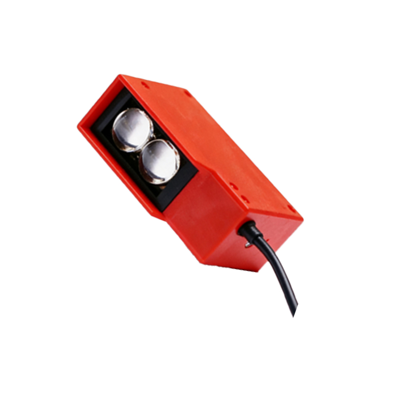
The BEN5M-MFR sensor typically features a pre-attached cable or a connector block with several color-coded wires. The standard wire color coding is as follows: Brown wire for the positive supply voltage (V+), Blue wire for the common negative or ground (0V), Black wire for the output signal (NO/NC), and White wire often used for a complementary output or function control. It is crucial to consult the specific datasheet for your model, as configurations can vary between diffuse, retro-reflective, and through-beam types. Identifying each terminal's purpose is the first critical step before proceeding with any electrical connections.
Power Supply Connection Requirements
The sensor operates on a DC power supply, commonly in the range of 10-30 VDC. Connect the Brown wire to the positive terminal (+) of your DC power source. Connect the Blue wire to the negative terminal (-) or ground of the same power source. Ensuring a stable and clean power supply within the specified voltage range is essential to prevent sensor malfunction or damage. Always use a regulated power supply and consider adding an inline fuse for circuit protection. Verify polarity before energizing the circuit to avoid irreversible damage to the sensor's internal electronics.
Output Signal Wiring Configuration
The Black wire is the primary output. The BEN5M-MFR usually offers a transistor output (NPN or PNP). For an NPN (sinking) output, the Black wire switches the load to ground (0V). The load (e.g., a PLC input, relay coil) is connected between the positive supply (V+) and the Black wire. For a PNP (sourcing) output, the Black wire switches the positive voltage to the load. Here, the load is connected between the Black wire and ground (0V). The White wire, if present, may be used for an opposite logic output or to enable special functions like teaching mode; refer to the manual for its specific use in your model.
Connecting to a Programmable Logic Controller (PLC)
When interfacing with a PLC, determine the PLC input type (sinking or sourcing). For a sinking PLC input (common positive), use an NPN sensor output. Connect the sensor's Black wire to the PLC input terminal, and the Blue wire to the PLC's common ground. For a sourcing PLC input (common negative), use a PNP sensor. Connect the sensor's Black wire to the PLC input, and the Brown wire (via the power supply) to the PLC's common positive. Always ensure the sensor and PLC share the same ground reference for reliable signal communication and to avoid ground loop issues.
Wiring for Load Devices like Relays or Lamps
For direct control of small relays, indicator lamps, or buzzers, connect the load in series with the sensor's output. Using an NPN configuration as an example: one terminal of the relay coil connects to V+ (Brown wire path), and the other terminal connects to the sensor's Black output wire. When the sensor detects an object, the internal transistor switches on, completing the circuit to ground (Blue wire) and energizing the relay. Ensure the load's current and voltage ratings are within the sensor's maximum switching capacity, typically specified in the datasheet, to avoid overloading the output circuit.
Shielded Cable and Noise Reduction Practices
In electrically noisy industrial environments, proper shielding is vital. If using a shielded cable, connect the drain wire or shield braid only at one end—typically at the control panel ground—to prevent ground loops. Keep the sensor wiring separate from high-voltage AC lines and motor drive cables. Use conduit or dedicated cable trays for separation. Implementing these electromagnetic compatibility (EMC) practices minimizes the risk of false triggering or signal interference, ensuring consistent and accurate sensor operation in complex automation systems.
Safety Precautions and Testing Procedures
Before applying power, double-check all wiring connections against the diagram. Use appropriate wire gauges and secure terminals to prevent loose connections. After powering on, verify the sensor's indicator LED behavior: a stable power LED indicates correct voltage, and the output LED should activate upon detection. Test the sensing function with the target object at the required distance. If malfunctions occur, systematically check power voltage, wiring continuity, load compatibility, and environmental factors like ambient light or dirt on the lens.
Troubleshooting Common Wiring Issues
Common problems often stem from incorrect wiring. No power or LED indication usually points to reversed polarity, blown fuse, or incorrect voltage. An output that is always on or off may indicate a mismatch between sensor output type (NPN/PNP) and load configuration, or a short/open circuit in the wiring. Inconsistent detection can be due to electrical noise, insufficient supply current, or incorrect sensing mode selection. Always isolate the issue by testing the sensor independently with a known-good load, such as a multimeter or a simple test lamp, before investigating the broader control system.
Conclusion and Best Practices
Correctly wiring the BEN5M-MFR photoelectric sensor is straightforward when following the manufacturer's diagram and understanding basic DC sinking/sourcing concepts. Key best practices include: always referencing the official datasheet, using a stable power supply, correctly matching output types with load circuits, implementing noise protection, and performing thorough post-installation testing. Proper installation not only guarantees reliable operation but also extends the sensor's service life, contributing to the overall efficiency and safety of your automated machinery and production lines.