Introduction to Proximity Switch Sensors
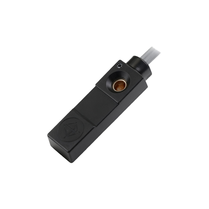
Proximity switch sensors, particularly the 3-wire M3 threaded variants, are fundamental components in modern industrial automation. These non-contact sensors detect the presence or absence of metallic objects without physical touch, ensuring reliability and longevity in demanding environments. The "3-wire" designation refers to the standard wiring configuration—typically comprising power (brown), ground (blue), and signal output (black) wires—which interfaces seamlessly with programmable logic controllers (PLCs) and other control systems. The M3 metric thread specifies a compact housing design, making these sensors ideal for applications with severe space constraints. Their operation is based on electromagnetic principles, where an oscillator circuit generates a high-frequency field. When a metallic target enters this field, it induces eddy currents, causing a change in the oscillator's amplitude. This change is detected and converted into a clean, digital output signal, triggering an action in the control system.
Key Technical Specifications and Selection Criteria
Selecting the appropriate 3-wire M3 proximity sensor requires careful consideration of several technical parameters. The sensing distance, or nominal range, is critical; for M3 models, this typically ranges from 0.5 to 1.5 mm, depending on the target material (e.g., mild steel, stainless steel, aluminum). Engineers must account for the reduction factor for non-ferrous metals. The operating voltage is another vital factor, with common DC versions operating at 10-30 VDC. The output type must be specified: NPN (sinking) or PNP (sourcing), which determines how the sensor interfaces with the common ground or positive voltage rail of the control system. Other essential specifications include the switching frequency (how many operations per second), temperature range (often -25°C to +70°C), housing material (typically nickel-plated brass or stainless steel for the M3 thread), and the IP (Ingress Protection) rating, such as IP67, which guarantees protection against dust and temporary immersion.
Wiring Configuration and Electrical Integration
Correct wiring is paramount for the safe and reliable operation of 3-wire DC proximity sensors. The standard color coding (brown: +V, blue: 0V/GND, black: output) is almost universally adopted. For a PNP (sourcing) sensor, the black wire outputs a positive voltage signal when a target is detected. This wire is connected to the input channel of a PLC. For an NPN (sinking) sensor, the black wire sinks current to ground when active, connecting to the PLC input configured for sinking signals. A critical step is always connecting a protective load resistor or ensuring the PLC input module has an integrated one to prevent damage from residual currents. M3 sensors, due to their small size, often come with pre-wired cables or compact connectors. Proper shielding and routing of cables away from high-voltage power lines are necessary to prevent electromagnetic interference (EMI) from causing false triggering or signal degradation.
Typical Industrial Applications and Mounting Considerations
The compact M3 form factor makes these sensors indispensable in precision machinery and densely packed assemblies. Common applications include position verification of tiny components in semiconductor manufacturing, end-of-travel detection in miniature linear actuators, and part presence checking in small-scale automated assembly cells. In robotic grippers, M3 sensors confirm whether a part has been successfully picked. Correct mounting is crucial for consistent performance. The sensor should be mounted securely using its M3 thread, often with a lock nut, to prevent vibration-induced loosening. Engineers must ensure that only the specified sensing face is exposed to the target; metallic surroundings (like a steel mounting bracket) can reduce the effective sensing range if they encroach on the sensor's electromagnetic field. Flush-mountable models are available to allow installation in metal structures without loss of range.
Maintenance, Troubleshooting, and Best Practices
While known for durability, 3-wire M3 proximity switches require periodic checks. Maintenance involves inspecting the sensing face for contamination like metal chips, oil, or coolant, which can attenuate the sensing field. The housing and cable should be checked for physical damage. Common troubleshooting steps include verifying power supply voltage at the sensor's terminals, checking for correct wiring against the datasheet, and using a multimeter to see if the output signal toggles when a target is presented. A frequent issue is incorrect sensor type (NPN vs. PNP) for the control system input. Best practices for optimal lifecycle include using sensors with a 10-20% duty cycle below their maximum rated sensing distance, implementing surge protection devices in circuits with inductive