Introduction to Photoelectric Sensor Circuits
Photoelectric sensor circuits are fundamental components in modern industrial automation, enabling non-contact detection of objects, distances, and surface conditions. These circuits operate by emitting light—typically infrared, visible, or laser—and detecting changes in the received light intensity or reflection patterns. The core principle involves converting optical signals into electrical signals, which are then processed to trigger outputs for control systems. Key elements include a light source (LED or laser diode), a photodetector (phototransistor, photodiode, or photoresistor), and signal conditioning circuitry. The design must account for environmental factors like ambient light interference, dust, and temperature variations to ensure reliable operation in harsh industrial settings. By leveraging modulation techniques and specialized optics, photoelectric sensors achieve high precision and immunity to noise, making them indispensable in manufacturing, packaging, robotics, and safety systems.
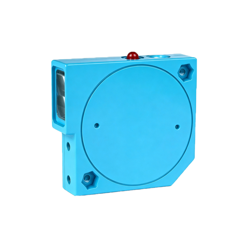
Circuit Components and Their Functions
A typical photoelectric sensor circuit comprises several critical components. The emitter section features a light-emitting diode (LED) or laser diode driven by a constant current source to maintain stable light output. Infrared LEDs are common due to their efficiency and minimal interference with visible light. The receiver section includes a photodetector, such as a phototransistor, which converts incident light into a proportional current. This weak signal is amplified using operational amplifiers (op-amps) in transimpedance or voltage amplifier configurations. Additional components like filters (e.g., band-pass filters for modulated light) and comparators help distinguish the signal from background noise. Power supply regulation, often via voltage regulators, ensures consistent performance. For digital output, Schmitt triggers or microcontroller interfaces provide clean switching signals. Enclosures with lenses or apertures focus light and protect components, enhancing sensitivity and durability.
Design Considerations for Industrial Applications
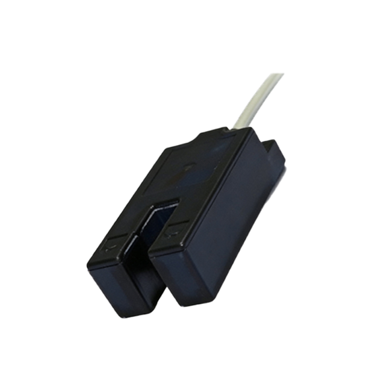
Designing photoelectric sensor circuits for industrial use requires addressing robustness and reliability. First, select components with appropriate ratings for temperature ranges (e.g., -25°C to 70°C) and ingress protection (IP67 or higher). Circuit layout should minimize noise by separating analog and digital sections, using shielded cables, and implementing ground planes. Modulation techniques, such as pulsing the emitter at a specific frequency, allow the receiver to filter out ambient light, improving signal-to-noise ratio. Sensitivity adjustments via potentiometers or digital trims enable customization for different materials and distances. Fail-safe features, like self-monitoring for emitter degradation, prevent malfunctions. Compliance with standards (e.g., IEC 60947-5-2) ensures safety and interoperability. Testing under real-world conditions—such as varying object colors, reflectivity, and speeds—validates performance before deployment.
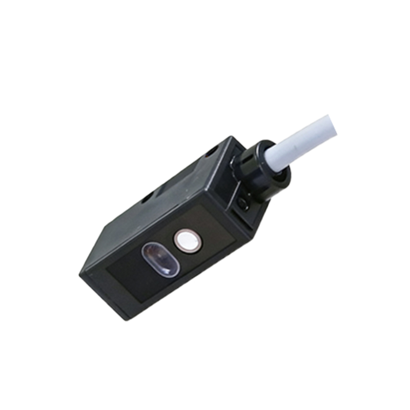
Common Circuit Configurations and Modes
Photoelectric sensors operate in three primary modes: through-beam, retroreflective, and diffuse reflective. In through-beam mode, separate emitter and receiver units face each other; object detection occurs when the beam is interrupted. This mode offers long range and high accuracy but requires alignment. Retroreflective mode uses a single unit with a reflector; the receiver detects light bounced back, and objects break the beam. It simplifies installation but may be affected by reflective surfaces. Diffuse reflective mode relies on light reflecting directly off the target, with the emitter and receiver in one housing. It’s compact but sensitive to color and texture. Circuit designs vary accordingly: through-beam circuits prioritize receiver sensitivity, while diffuse types incorporate background suppression via triangulation or time-of-flight techniques. Analog outputs provide continuous distance data, whereas digital outputs offer simple on/off signals.
Integration with Control Systems and Future Trends
Integrating photoelectric sensors into industrial control systems involves interfacing with PLCs, microcontrollers, or networked devices. Outputs typically include NPN/PNP transistors, relay contacts, or serial communication (e.g., IO-Link). Circuits may include diagnostics like LED indicators for status or fault detection. Advanced sensors feature smart capabilities, such as programmable logic, data logging, and connectivity to Industrial Internet of Things (IIoT) platforms. Emerging trends focus on miniaturization, higher precision with laser-based sensors, and energy-efficient designs. Innovations like multispectral sensors that detect beyond visible light, and AI-enhanced signal processing, are expanding applications in quality inspection and predictive maintenance. As industries adopt Industry 4.0, photoelectric sensor circuits will evolve toward greater intelligence and seamless integration, driving efficiency and automation forward.