Understanding Proximity Sensor Fundamentals
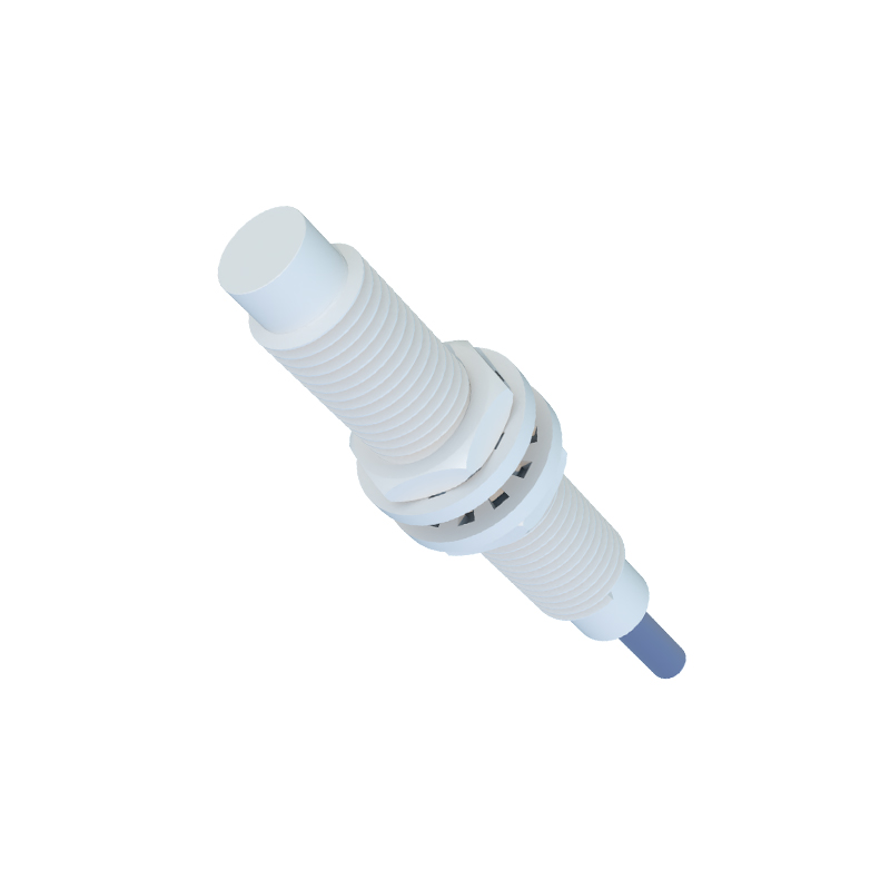
High-tech proximity sensors, including inductive, capacitive, and ultrasonic types, are non-contact devices that detect the presence or absence of an object. Before wiring, it is critical to understand the sensor's specifications: operating voltage (commonly 10-30V DC or 90-250V AC), output type (PNP/NPN sourcing/sinking, NO/NC), and sensing range. Always consult the manufacturer's datasheet. The core principle involves the sensor receiving power, generating an electromagnetic or ultrasonic field, and providing a switched signal output when a target enters its detection zone. Incorrect wiring can lead to immediate device failure or erratic operation.
Power Supply Connections and Requirements
A stable, clean power supply is paramount. For DC sensors, typically a 24V DC supply is used. Connect the positive voltage wire (often brown or red) to the positive terminal marked V+ or +Vs. Connect the negative or 0V wire (often blue or black) to the terminal marked 0V, COM, or GND. For AC sensors, connect the Line (L) and Neutral (N) wires to the corresponding terminals. Ensure the power supply's current rating exceeds the sensor's consumption, especially when multiple sensors are connected. Implement appropriate fusing and consider using a separate, dedicated power supply for sensitive sensor arrays to avoid noise interference from other machinery.
Output Signal Wiring Configuration
The output wiring depends entirely on the sensor's transistor type and the load's requirements. A PNP (sourcing) sensor switches the positive voltage to the load. Wire the sensor's output signal wire (usually black) to one terminal of the load (e.g., a PLC input). Connect the other load terminal to the power supply's 0V (COM). An NPN (sinking) sensor switches the 0V path. Wire the sensor's output to the load, and connect the other load terminal to the positive voltage. For a Normally Open (NO) configuration, the output is off with no target; it turns on when detected. For Normally Closed (NC), the opposite is true. Always verify the PLC or controller input is compatible (sinking vs. sourcing).
Implementing Shielded Cabling and Grounding
To ensure reliable operation in electrically noisy industrial environments, proper shielding and grounding are non-negotiable. Use shielded, twisted-pair cables. Connect the cable's drain wire or shield braid to the functional earth (FE) or ground terminal on the sensor housing, if provided. At the control panel end, connect this shield to a clean earth ground point at one end only (typically the control panel side) to prevent ground loops. Keep sensor cables separate from high-voltage power lines and motor drives. Route them in separate conduits or trays. This practice minimizes electromagnetic interference (EMI) and capacitive coupling, which can cause false triggering.
Wiring for Specific Sensor Types and Features
Advanced sensors may have additional connections. For instance, a 4-wire sensor might have two for power and two independent outputs (e.g., one PNP and one NPN). Analog output sensors (e.g., 4-20mA or 0-10V) require wiring the analog output wire to the analog input module, with proper attention to signal common. Sensors with diagnostic outputs (like IO-Link) require a dedicated 3-wire connection for digital communication alongside power. For two-wire AC/DC sensors, they are wired in series with the load, simplifying installation but requiring careful calculation of residual current and voltage drop. Always follow the specific terminal diagram for your model.
Testing, Troubleshooting, and Safety Protocols
After wiring, perform a systematic test. Apply power and use the sensor's built-in LED indicator (if available) to verify power and output status. Bring a target into the sensing field. Use a multimeter to check voltage at the output terminal relative to COM. For persistent issues, check for wiring errors, insufficient power supply, excessive load current, or electrical noise. Ensure all connections are tight and corrosion-free. Adhere to lock-out/tag-out (LOTO) procedures before handling any wiring. Never exceed the sensor's maximum voltage or current ratings. Implementing these steps ensures a robust, fail-safe installation that maximizes sensor longevity and system uptime.