Understanding the Retroreflective Photoelectric Sensor
A retroreflective photoelectric sensor, often called a reflex sensor, is a cornerstone of industrial automation. Its operation is elegantly simple: the sensor unit emits a beam of light, typically from an LED, towards a dedicated reflector. This reflector, constructed with a special prismatic surface, returns the light beam directly back to its source along the same path. The sensor's receiver detects this returned light. An object passing between the sensor and the reflector interrupts this beam, causing the receiver to lose the signal and triggering the sensor's output to change state. This non-contact detection method is prized for its reliability, long sensing range, and relatively straightforward installation compared to through-beam systems, as it requires wiring only on one side of the detection point.
Essential Pre-Test Preparations and Safety
Before initiating any testing procedure, thorough preparation is critical for both safety and accuracy. First, consult the sensor's datasheet. Identify its specific voltage range (e.g., 10-30 VDC), output type (PNP/NPN, NO/NC), and connection diagram. Ensure the power supply is disconnected during initial wiring. Visually inspect the sensor, reflector, and cabling for any signs of physical damage, corrosion, or contamination like dust, oil, or moisture on the lenses. Verify the mounting alignment; even a few degrees of misalignment can drastically reduce performance. The sensor and reflector must be securely fastened to prevent vibration-induced misalignment. Finally, confirm the operating environment is within the sensor's specified ratings for temperature, humidity, and resistance to chemicals.
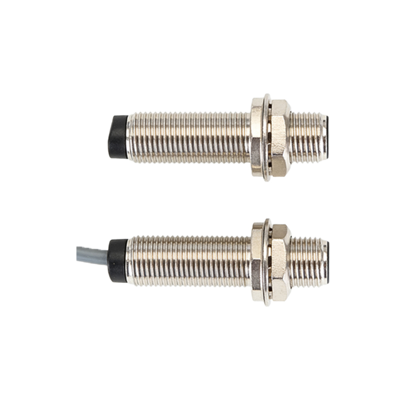
Step-by-Step Electrical and Functional Testing
Begin by applying the correct power to the sensor. Most modern sensors feature a built-in indicator LED (often green for power and yellow/red for output activation). A steady green light confirms power is present. Next, perform a basic function test. Without an object in the sensing path, the output indicator should be in its default state (e.g., off for a normally-open configuration). Carefully introduce a test object of the minimum specified size and reflectivity into the beam. The output indicator should change state (e.g., turn on) and return to default when the object is removed. Use a digital multimeter to measure the output signal. For a PNP sensor, you should measure near the supply voltage (e.g., 24V) at the output wire when activated, and nearly 0V when not activated.
Evaluating Sensing Range and Beam Integrity
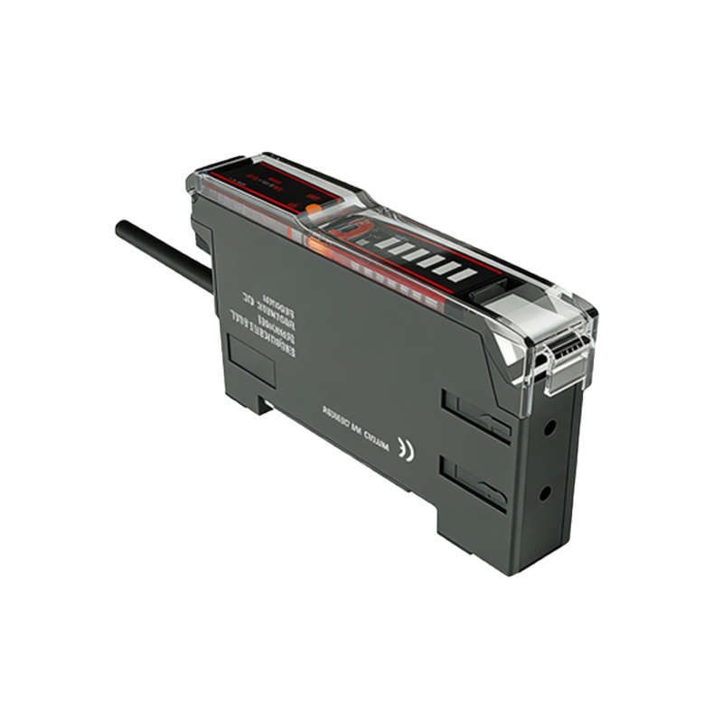
Sensing range is a key parameter. Using a non-reflective test object, gradually move it towards the sensing beam from the side, noting the exact distance at which the sensor triggers. Compare this to the datasheet's "assured operating distance." For long-range sensors, this test is crucial. To check beam integrity and alignment, a specialized retroreflective sensor tester or an alignment rod is invaluable. These tools often have a graduated scale showing signal strength. Insert the tester in the beam path and rotate it. A consistent, high signal strength reading across multiple points indicates excellent alignment and a clean optical path. A fluctuating or weak signal suggests misalignment or lens contamination.
Troubleshooting Common Performance Issues
If the sensor fails to operate, follow a logical diagnostic sequence. *No Power Indicator:* Verify wiring polarity and voltage. Check for blown fuses or tripped circuit breakers. *Power On, No Output Change:* This is the most common issue. Re-check alignment meticulously. Clean the sensor and reflector lenses with a soft, lint-free cloth and appropriate cleaner. Ensure the test object is large and opaque enough. Check for environmental interference like intense ambient light (sunlight, welding arcs) which can swamp the receiver; shading the sensor may help. Verify that the object isn't highly reflective, which could return enough light to keep the sensor in its "beam present" state. *Inconsistent or Chattering Output:* This often points to a marginal alignment, a vibrating mounting surface, or a dirty lens causing a weak signal. Secure the mounting and re-align.
Advanced Diagnostics and Maintenance Practices
For persistent issues, advanced tools provide deeper insight. An oscilloscope can monitor the modulated light signal, revealing noise or instability invisible to a multimeter. Monitoring the sensor's current draw can also indicate health; a significant deviation from the typical quiescent current may signal internal component failure. For maintenance, establish a regular schedule. Periodically clean optical surfaces, even in clean environments, as thin films can develop. Check and re-tighten mounting hardware, as thermal cycles and vibration can cause loosening. Log the performance baseline (triggering distance, signal strength) during installation to facilitate future comparative diagnostics. Always keep critical spares, especially for sensors in high-availability processes.