What is Through-Beam Photoelectric Sensor Frequency?
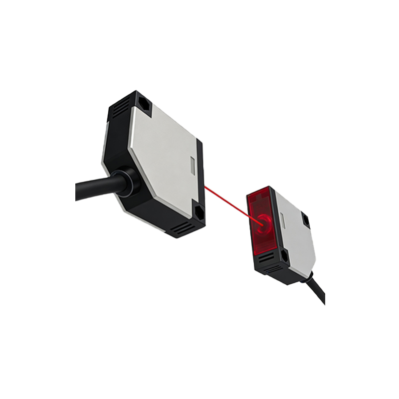
Through-beam photoelectric sensor frequency, often referred to as response frequency or switching frequency, is a critical performance parameter. It defines the maximum number of detection operations (ON/OFF cycles) a sensor can perform per second, measured in Hertz (Hz). This specification determines how fast a sensor can detect objects passing through its beam. In high-speed automation, packaging, and material handling applications, a sensor with an insufficient frequency rating may miss objects, leading to production errors. The frequency is inherently linked to the sensor's internal electronics and the time required for the output signal to stabilize after each state change. Understanding this fundamental specification is the first step in selecting the right sensor for speed-critical tasks.
Key Factors Influencing Sensor Frequency
Several core factors dictate the maximum achievable frequency of a through-beam sensor. The primary factor is the physical design and quality of the photoelectric receiver and emitter components. Advanced components with fast light reception and processing capabilities enable higher frequencies. Secondly, the output circuit type plays a significant role. Sensors with transistor outputs (NPN or PNP) typically offer much higher frequencies—often ranging from 500 Hz to several kHz—compared to mechanical relay outputs, which are slower due to physical moving parts. The sensing distance also indirectly affects performance; over very long distances, the light signal weakens, potentially requiring more processing time and slightly reducing effective response speed. Finally, environmental conditions like ambient light interference or contamination on lenses can force the sensor's circuitry to work harder, potentially impacting its maximum operational frequency.
Typical Frequency Ranges and Specifications
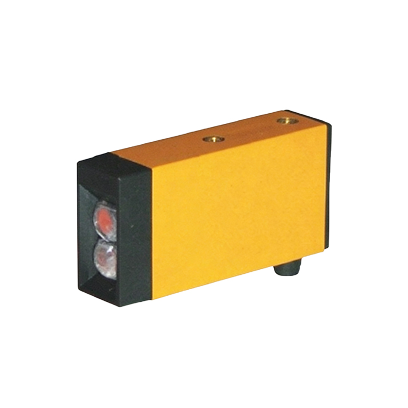
The frequency specification varies widely across different models and manufacturers. Standard through-beam sensors commonly offer frequencies in the range of 100 Hz to 2,000 Hz (2 kHz). For general-purpose industrial applications, a frequency of 200-500 Hz is often sufficient. However, specialized high-speed models are available with frequencies exceeding 10 kHz. It is crucial to consult the manufacturer's datasheet for the exact specification, usually listed as "Response Frequency" or "Switching Frequency." The datasheet will also specify conditions for this rating, such as the test distance and the size of the object used. A 1 kHz sensor, for example, can theoretically detect 1,000 objects per second, but this assumes an object size and beam interruption pattern that allows the output to fully cycle between states.
How to Calculate Required Frequency for an Application
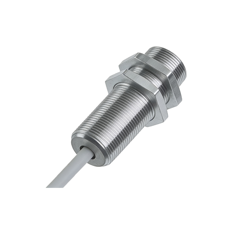
Selecting a sensor with an appropriate frequency requires a simple calculation based on application parameters. The key variables are the speed of the object (V) and its size or the gap between objects (D). The fundamental formula is: Required Frequency (Hz) = Object Speed (mm/s or m/s) / Object Size or Gap (mm or m). For instance, if small components on a conveyor are traveling at 2 meters per second and are spaced 10mm apart, the required frequency would be 2000 mm/s / 10 mm = 200 Hz. It is a universal best practice to select a sensor with a rated frequency at least 1.5 to 2 times higher than this calculated value. This safety factor accounts for real-world variables like inconsistent spacing, vibration, and ensures reliable operation without missing triggers at the system's maximum speed.
Impact of Frequency on High-Speed Automation
In modern high-speed automation, the frequency of a through-beam sensor is a direct enabler of throughput and precision. On bottling lines, packaging machinery, or electronic component assembly, sensors with high frequencies (1 kHz to 10 kHz) ensure every item is counted, positioned, or inspected without error at extreme speeds. A low-frequency sensor becomes a bottleneck, limiting the entire machine's cycle time. Furthermore, high-frequency sensors provide more precise timing data, which is essential for synchronization with robotic arms, servo drives, and vision systems. The fast, clean switching signal they generate minimizes latency in the control system, leading to tighter tolerances, reduced waste, and higher overall equipment effectiveness (OEE).
Optimizing and Troubleshooting Frequency-Related Issues
If a sensor is suspected of missing detections due to frequency limitations, a systematic approach is required. First, verify the application's required frequency using the mentioned calculation and compare it to the sensor's datasheet rating. Ensure the sensor is not being operated at its absolute limit; derating is recommended. Check for external factors that can degrade effective performance: dirty lenses, misalignment causing a weak signal, or strong ambient light from welding or sunlight. Using a sensor with a modulated (pulsating) light source can improve immunity to such interference. For the fastest applications, consider sensors specifically marketed as "high-speed" and ensure the connected controller (PLC) input card is also rated for high-speed signals. Regular maintenance and alignment checks are paramount to sustaining optimal frequency performance over time.