Understanding Digital Photoelectric Sensor Basics
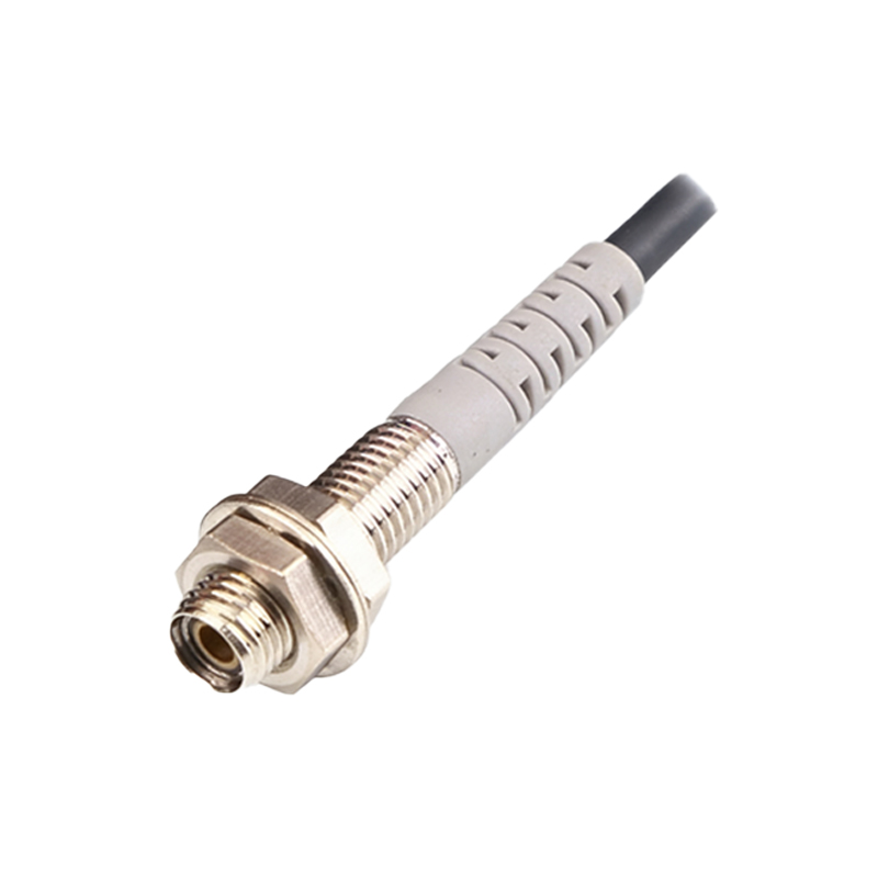
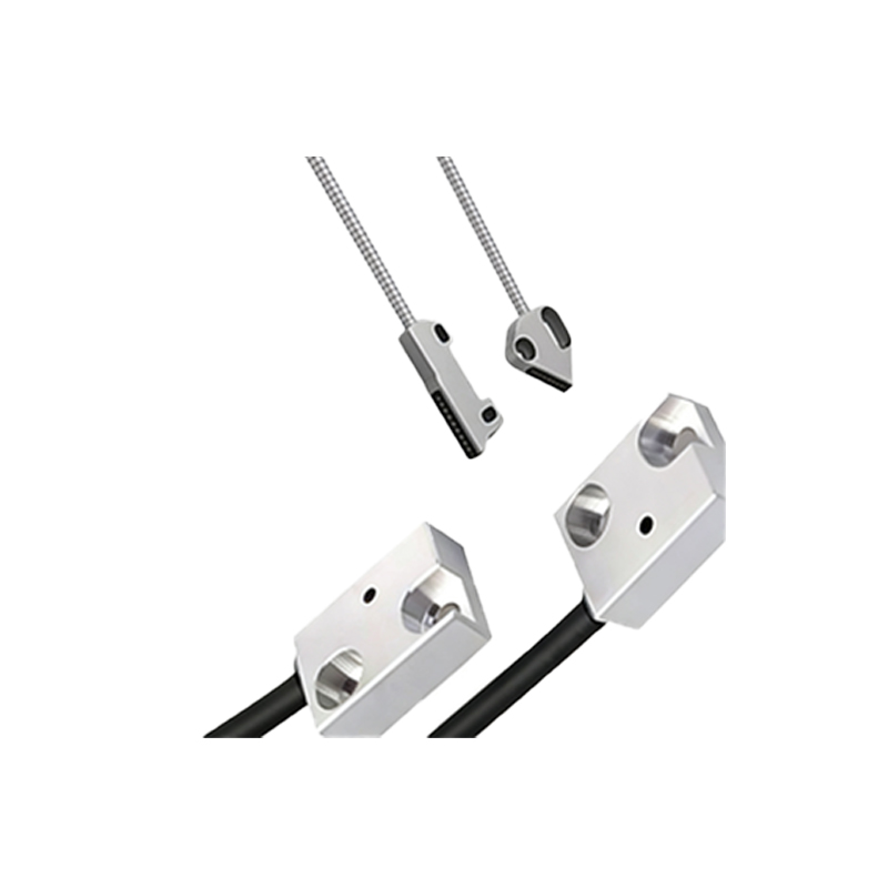
Digital photoelectric sensors are fundamental components in industrial automation, used for detecting the presence, absence, or position of objects without physical contact. Unlike their analog predecessors, digital models provide clear, on/off output signals and often feature built-in indicators and adjustment interfaces. The core principle involves an emitter (usually an LED) projecting a light beam—visible, infrared, or laser—toward a receiver. Detection occurs when this beam is either interrupted (opposed mode) or reflected back (retro-reflective or diffuse mode). Before any adjustment, it is critical to confirm the sensor's specific operating mode, as the adjustment procedure and parameters differ significantly. A thorough review of the manufacturer's datasheet for voltage requirements, output type (NPN/PNP), and sensing range is the essential first step in any setup process.
Pre-Adjustment Preparation and Safety
Prior to making any adjustments, ensure the system is in a safe state. Lock out and tag out (LOTO) the machinery's power source to prevent accidental activation. Verify the sensor is correctly mounted and aligned according to the application's specifications. Check all electrical connections for integrity, confirming the power supply matches the sensor's rated voltage (e.g., 10-30V DC). Inspect the lens for dust, oil, or debris that could scatter or block the light beam, as a clean optical path is paramount for reliable operation. Have the necessary tools ready, which typically include a small screwdriver for potentiometer adjustments and the sensor's instruction manual. For sensors with teach-in or push-button programming functions, familiarize yourself with the button sequences.
Initial Power-Up and Mode Selection
Apply power to the sensor circuit. Most digital photoelectric sensors feature a status LED that indicates power (often green) and output state (often orange or red). Observe these indicators. The first adjustment step typically involves selecting the correct operating mode via a selector switch or internal DIP switches. Common modes include Light-ON (output activates when light is received) and Dark-ON (output activates when light is blocked). For diffuse sensors, you may also select background suppression mode for precise detection at a fixed distance, ignoring objects beyond it. Ensure the mode aligns with your control logic; for instance, a safety interlock usually requires a Dark-ON mode so that a beam break triggers the safe state.
Adjusting Sensitivity and Threshold
Sensitivity adjustment is the most critical calibration step. Digital sensors use a potentiometer or digital buttons to set the detection threshold. For a thru-beam or retro-reflective sensor, place the target object in the detection path. Slowly rotate the sensitivity potentiometer counterclockwise until the output LED turns off (or on, depending on mode), indicating the sensor is at the threshold of detection. Then, rotate it clockwise approximately 1.5 to 2 turns to provide an adequate operating margin, accounting for environmental variations like accumulated dust or minor misalignment. For diffuse sensors, use the actual target object at the desired detection distance. Some advanced models feature a "teach" button: present the target and press the button to automatically set the threshold. Always test with the object slightly off-center to ensure a robust detection window.
Setting Response Time and Hysteresis
Many digital photoelectric sensors allow adjustment of response time or signal delay. This parameter filters out rapid signal fluctuations caused by vibration, spray, or small passing objects. For high-speed applications, set the response time to "fast." For environments with interference, a longer response time (e.g., 10-50ms) can stabilize the output. Hysteresis, the difference between the turn-on and turn-off points, is often factory-set but may be adjustable. A wider hysteresis prevents output chattering when an object is positioned at the exact threshold point. Adjust this based on the required precision and the stability of the target object's position.
Fine-Tuning for Challenging Conditions
Challenging materials (transparent, shiny, or dark) and harsh environments require fine-tuning. For clear glass or plastic, consider using a polarized retro-reflective sensor or a high-power laser sensor. Adjust the sensitivity very carefully, as over-amplification can cause detection of background objects. For shiny surfaces, tilt the diffuse sensor at a slight angle to avoid direct specular reflection back to the receiver. In dusty or foggy conditions, increase the sensitivity margin and implement regular lens cleaning schedules. For outdoor use, select sensors with robust housings (IP67/IP69K) and adjust for ambient light immunity, often a separate potentiometer or setting that ignores gradual light changes.
Verification and Troubleshooting Procedures
After adjustment, conduct comprehensive verification. Test detection with the target object across the entire required range of positions. Introduce potential interferents, like passing non-target objects or varying ambient light. Monitor the output with a multimeter or PLC input indicator to ensure a clean, stable signal. Common issues include inconsistent detection (often due to insufficient sensitivity margin), false triggers (caused by reflective backgrounds or electrical noise), or no output. Systematic troubleshooting involves checking alignment, cleaning lenses, verifying power and wiring, and confirming the load (e.g., PLC input) is correctly connected and within specifications. Revisit the sensitivity adjustment if performance is erratic.
Documentation and Long-Term Maintenance
Once optimal settings are achieved, document them. Note the positions of all potentiometers or record the digital configuration codes. This facilitates quick recovery after a power loss or sensor replacement. Implement a preventive maintenance schedule. Periodically inspect the sensor for physical damage, cleanliness, and secure mounting. Re-verify the adjustment under operating conditions at regular intervals, as lens contamination or component aging can drift the sensing characteristics. For critical applications, consider installing redundant sensors or using models with diagnostic output that signal lens contamination or marginal operating conditions, enabling proactive maintenance before a failure occurs.