Introduction to the 9108 Proximity Sensor Series
The 9108 series represents a robust line of inductive proximity sensors designed for demanding industrial environments. These sensors are engineered to detect metallic objects without physical contact, utilizing an electromagnetic field to sense the presence of ferrous and non-ferrous metals. Key specifications typically include a defined sensing range, various housing materials like nickel-plated brass or stainless steel, and output configurations such as NPN or PNP. Their primary function is to provide reliable position feedback, object detection, or counting in automated machinery, conveyor systems, and safety interlocks. Understanding the fundamental operating principle—where a metallic target entering the sensing field dampens the oscillation amplitude in the sensor's LC tank circuit, triggering a state change—is crucial for effective testing.
Essential Pre-Test Preparations and Safety
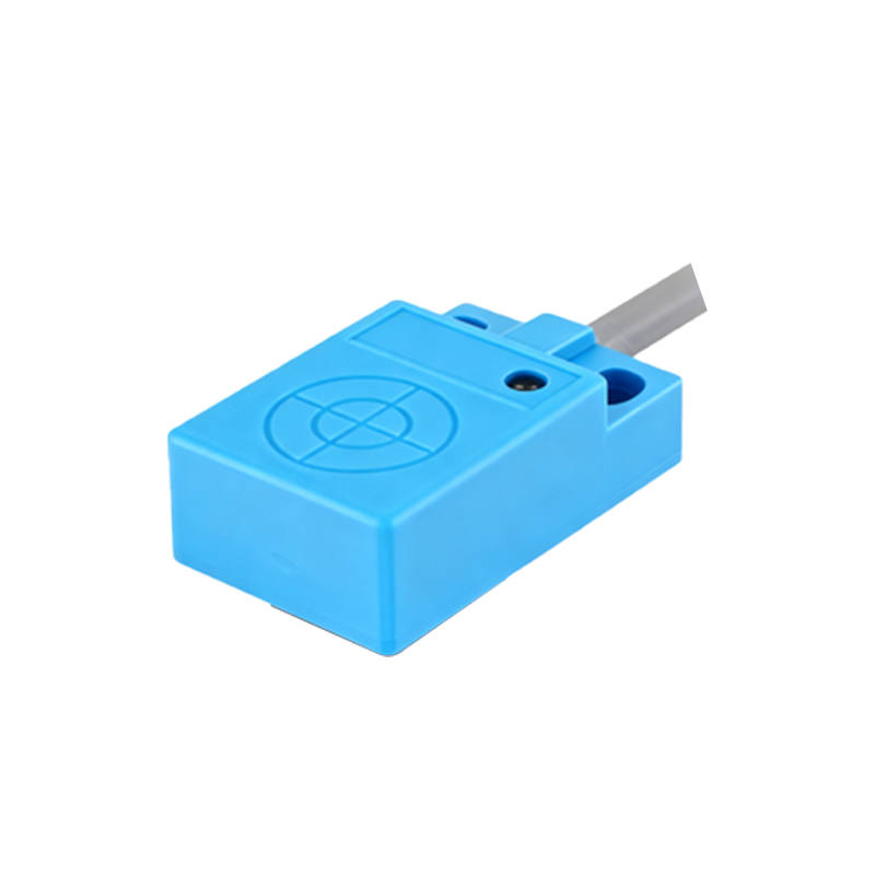
Prior to initiating any test procedure, comprehensive preparation is mandatory to ensure personnel safety and result accuracy. Begin by consulting the manufacturer's datasheet for the specific 9108 model to verify its electrical ratings, sensing distance, and environmental limits. Ensure the work area is clean, dry, and free from metallic debris that could interfere with readings. Required equipment includes a regulated DC power supply matching the sensor's voltage rating (commonly 10-30V DC), a digital multimeter, a set of precision metal targets (often supplied by the manufacturer), a calibrated distance gauge or micrometer, and an oscilloscope for advanced diagnostics. Always adhere to lock-out/tag-out (LOTO) procedures when integrating the test into a larger system and wear appropriate personal protective equipment (PPE).
Testing Sensing Range and Repeatability
The rated sensing distance (Sn) is a critical parameter. To test this, mount the sensor securely on a stable fixture. Connect it to the correct power supply and load (e.g., a pilot lamp or multimeter). Using the standard target specified in the datasheet (usually a square of mild steel), approach the sensor's active face axially. The switch-on point is determined when the output state changes as the target moves closer. Measure this distance precisely. Repeat this process at least 10 times to calculate the repeatability error, which should fall within the manufacturer's tolerance, often a percentage of Sn. Ambient temperature can affect this range, so testing under expected operational conditions is advised.
Evaluating Electrical Characteristics and Output
Electrical verification ensures the sensor interfaces correctly with control systems. First, measure the quiescent current draw when no target is present. Then, with a target well within the sensing range, measure the output voltage in the active state for a switching output, or the analog current level for analog variants. Check for leakage current in the "off" state, which should be minimal. For switching sensors, test the response time—both turn-on and turn-off delay—using an oscilloscope to trigger on the target's edge. This determines the maximum operational frequency. Additionally, perform a voltage tolerance test by varying the supply voltage within the specified range (e.g., from 10V to 30V DC) and confirming stable switching.
Environmental and Harsh Condition Testing
Industrial sensors must withstand harsh conditions. While not all tests are feasible in a standard workshop, key evaluations include checking the sensor's ingress protection (IP) rating. This can involve simple verification of seal integrity. Test for resistance to electrical noise by operating the sensor near sources of electromagnetic interference, such as variable frequency drives (VFDs) or welding equipment, and monitor for false triggering. Although full temperature cycle testing requires a chamber, one can verify operation at the expected ambient extremes. Furthermore, assess the housing's resistance to chemicals, oils, or coolants if used in such environments, following the material compatibility guidelines.
Diagnosing Common Failure Modes
During testing, several failure modes may be identified. A complete lack of output may indicate incorrect wiring, a damaged oscillator coil, or internal circuit failure. Intermittent operation can result from a loose connection, an unstable power supply, or a target that is too small, too slow, or outside the permissible material grade. Reduced sensing range often points to physical damage to the sensing face, buildup of metallic swarf, or degradation of internal components. False triggering is frequently caused by excessive sensor-to-sensor proximity (mutual interference), strong external magnetic fields, or electrical noise on the supply lines. Systematic isolation of variables is key to diagnosis.
Documentation and Final Performance Validation
Meticulous documentation of all test results is essential for quality assurance and maintenance records. Create a test log noting the sensor model, serial number, test date, environmental conditions,