Introduction to 3-Wire Proximity Sensors
In the realm of industrial automation, proximity sensors are indispensable components for non-contact object detection. Among the various configurations, the 3-wire DC proximity sensor stands as the most prevalent and versatile type. These sensors operate by generating an electromagnetic field and detecting changes caused by the presence of a metallic target within their sensing range. Unlike their 2-wire counterparts, 3-wire sensors provide a distinct separation between the power supply and the output switching circuit. This fundamental architecture offers significant advantages in reliability, performance, and ease of integration into complex control systems. They are the workhorses found on assembly lines, packaging machinery, robotic cells, and material handling equipment, providing the essential "eyes" for automated processes.
Internal Circuitry and Operating Principle
The core of a 3-wire DC sensor consists of an oscillator, a demodulator, a trigger circuit, and an output switching device. The oscillator generates a high-frequency electromagnetic field at the sensor's active face. When a metallic target enters this field, eddy currents are induced in the target, which dampens the oscillation amplitude. The demodulator converts this change into a DC signal, which the trigger circuit evaluates against a predefined threshold. Once the threshold is crossed, the trigger commands the output stage to change state. The three wires are clearly defined: one for DC supply voltage (typically brown wire), one for the common ground/return (typically blue wire), and one for the output signal (typically black wire for NPN or black/white for PNP). This dedicated output wire allows for a solid-state switch—either a transistor sinking current (NPN) or sourcing current (PNP)—to control the load.
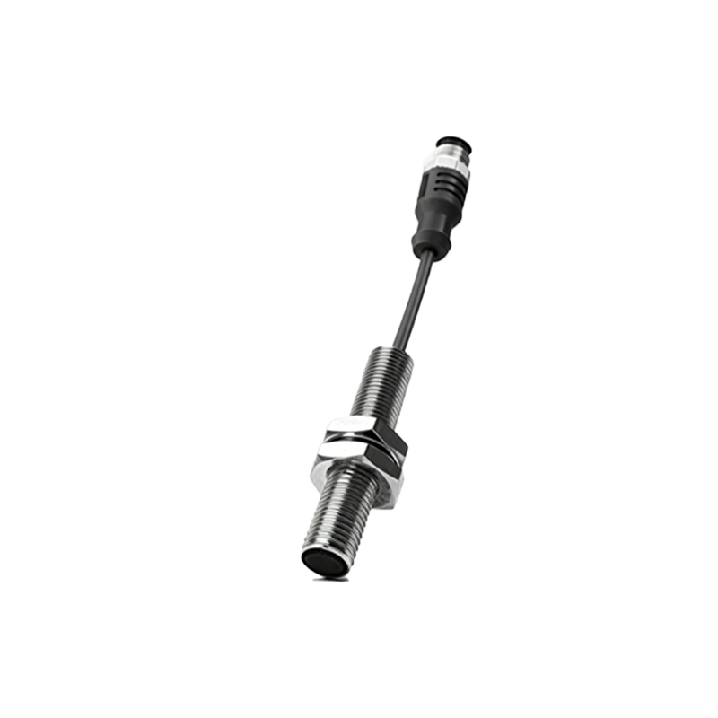
Wiring Configurations: NPN vs. PNP Outputs
A critical distinction in 3-wire sensors is the type of transistor output, classified as NPN or PNP. This designation determines how the sensor interfaces with the programmable logic controller (PLC) or other control devices. An NPN sensor, also known as a sinking sensor, switches the negative or ground side of the load. In a typical NPN wiring scheme, the load (e.g., a PLC input) is connected between the positive supply and the sensor's output wire. When activated, the NPN transistor closes the circuit to ground, allowing current to flow into the sensor's output. Conversely, a PNP sensor, or a sourcing sensor, switches the positive side of the load. Here, the load is connected between the sensor's output and ground. Upon detection, the PNP transistor provides the positive voltage from the output wire to the load. The choice between NPN and PNP is primarily dictated by the electrical conventions of the control system and the region.
Key Advantages Over 2-Wire Sensors

The three-wire design confers several operational benefits. First, it features a very low leakage current (off-state current), which minimizes the risk of falsely triggering a PLC input. Second, it allows for a higher switching current capacity, enabling it to drive heavier loads directly, such as small relays or indicator lamps. Third, the voltage drop across the output transistor is minimal, ensuring that the full supply voltage is effectively delivered to the load. This results in more stable performance, especially over long cable runs or in applications with fluctuating supply voltages. Furthermore, 3-wire sensors are less susceptible to electrical noise and can handle higher switching frequencies, making them suitable for high-speed counting and positioning tasks.
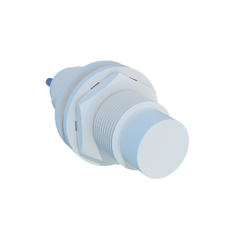
Critical Selection Parameters for Application
Selecting the correct 3-wire proximity sensor requires careful consideration of several parameters. The sensing distance, or nominal range, must be appropriate for the application, with a safety margin to account for mechanical tolerances and target variations. The target material is crucial; standard sensors are optimized for mild steel, while factors for stainless steel, aluminum, or copper are significantly lower. The housing style (cylindrical, rectangular, or ring-shaped) and size must fit the mechanical constraints. Environmental factors like temperature extremes, presence of cutting fluids, or washdown conditions dictate the required ingress protection (IP) rating. Finally, the electrical specifications—supply voltage range (commonly 10-30V DC), output type (NPN/PNP, normally open/closed), and current rating—must match the control system's requirements.
Installation and Troubleshooting Best Practices
Proper installation is paramount for reliable operation. Sensors must be mounted securely to prevent vibration-induced failure or sensing distance drift. A critical rule is to maintain adequate clearance between the sensor body and the metal mounting surface, as specified by the manufacturer, to prevent side-act