Understanding Through-Beam Photoelectric Sensors
Through-beam photoelectric sensors, also known as opposed-mode sensors, consist of two separate units: a transmitter and a receiver. The transmitter emits a continuous beam of light, typically infrared or laser, which is detected by the receiver. An object is sensed when it interrupts this beam. This configuration offers the longest sensing range and highest reliability among photoelectric sensor types, as it is less susceptible to environmental factors like target color, reflectivity, or surface finish. Proper adjustment is critical to ensure the sensor operates within its specified parameters, providing accurate and stable detection in industrial automation, packaging, material handling, and safety systems. The core principle is precise alignment; even a minor misalignment can lead to false triggers or failure to detect objects. Before beginning any adjustment, always consult the manufacturer's datasheet for specific specifications regarding sensing distance, beam characteristics, and environmental ratings.
Pre-Installation Planning and Safety
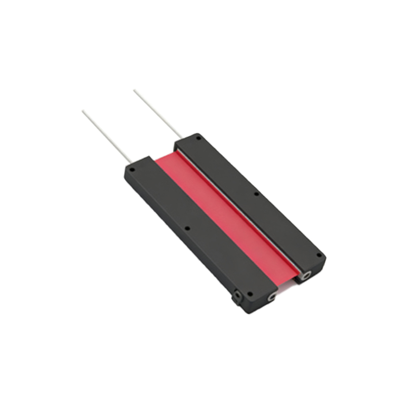
Safety is the foremost priority. Ensure the system's power is completely locked out and tagged out (LOTO) before handling any components. Select an appropriate location for mounting both the transmitter and receiver. Consider the application's requirements: the required sensing distance, the size of the objects to be detected, and the operating environment (presence of dust, moisture, vibration, or ambient light). The mounting surface must be stable and rigid to prevent shifts due to vibration. Use high-quality brackets designed for the specific sensor model to ensure secure fixation. Verify that the path of the light beam remains clear of potential obstructions, including moving machine parts, accumulated debris, or personnel walkways. Planning this path minimizes future maintenance issues and alignment drift.
Mechanical Mounting and Rough Alignment
Securely mount the transmitter and receiver units on opposite sides of the detection area using the provided hardware. Initially, perform a rough visual alignment. Many sensors feature built-in alignment aids such as through-hole sights or pilot beams (a visible red LED that coincides with the invisible infrared beam). Use these aids to coarsely align the two units so they are facing each other. The goal at this stage is to get the receiver within the general emission cone of the transmitter. Tighten the mounting hardware just enough to hold position but still allow for fine adjustment. For long-range applications, using a laser alignment tool or a telescopic sight can significantly speed up this process and improve initial accuracy.
Electrical Connection and Power-Up
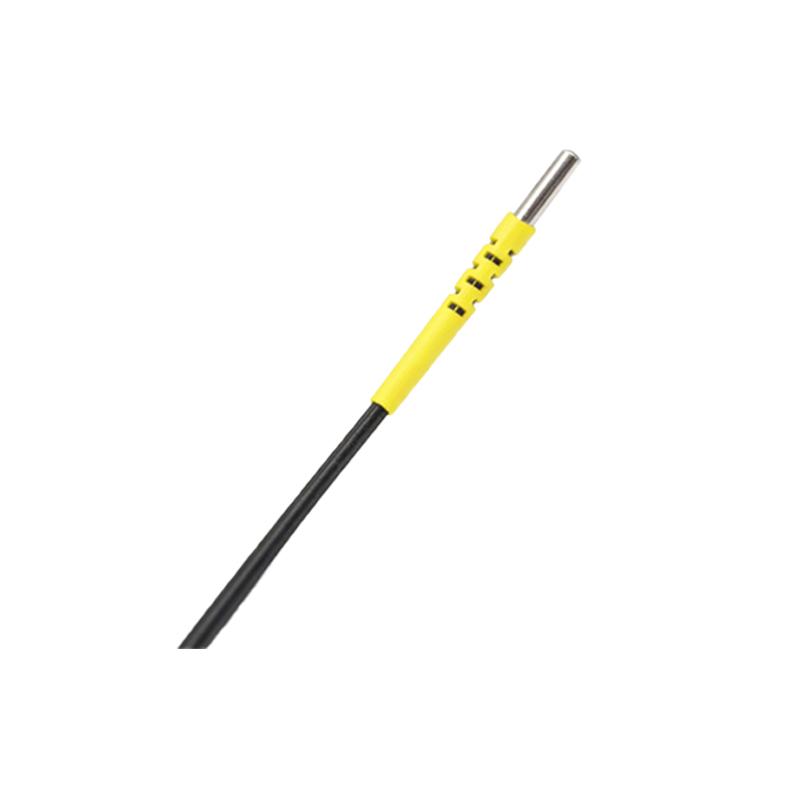
Following the wiring diagram in the sensor manual, connect the units to the appropriate power supply. Through-beam sensors typically have three or four wires: power (V+), ground (V-), and output signal(s). Double-check polarity to prevent damage. Once connections are secure and confirmed, apply power. Most modern sensors have indicator LEDs. The transmitter usually has a power or emission indicator, while the receiver has both a power indicator and a separate output or alignment indicator. The receiver's alignment indicator is crucial for the next step. It may be a single LED that changes color (e.g., from red to green) or a bar graph display showing signal strength as a percentage.
Fine-Tuning Alignment for Maximum Signal Strength
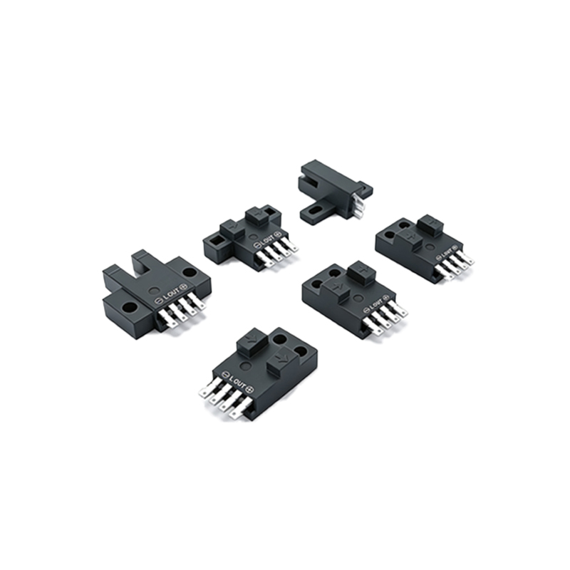
This is the most critical adjustment phase. Observe the receiver's alignment indicator. The objective is to maximize the received light signal. Gently adjust the position of either the transmitter or receiver in small increments—first horizontally, then vertically. Use the indicator's feedback; for a bar graph, aim for 100% or the highest stable reading. For a color-changing LED, achieve the stable "good alignment" state (e.g., solid green). Avoid the beam's "edge," where the indicator flickers between states, as this indicates marginal alignment prone to failure from minor vibrations. If available, use the sensor's potentiometer or teach-in button to set the sensitivity threshold after achieving peak alignment, ensuring a stable operating margin. Some advanced sensors feature automatic alignment or monitoring functions that simplify this process.
Verification and Testing Under Operational Conditions
After achieving optimal alignment and tightening all mounting hardware, conduct thorough testing. Introduce the target object into the beam path repeatedly. Verify that the sensor's output switches states reliably and consistently. Test with objects of different sizes if applicable. It is essential to test under real or simulated operational conditions. Run the surrounding machinery to check if vibrations cause the alignment to drift or the signal to become unstable. Observe the sensor's performance over an extended period, monitoring for any intermittent faults. For critical safety applications, this testing phase must be exhaustive and documented. Ensure that no external light sources (e.g., sunlight, welding arcs) are shining directly into the receiver, as this can cause interference.
Troubleshooting Common Alignment Issues
Several common problems can arise. If the receiver's alignment indicator shows no signal, verify power to both units, check for complete beam obstruction, and re-attempt rough alignment. A weak or unstable signal often points to misalignment, dirty lenses, or excessive distance. Clean the lenses with a soft cloth. If the sensor false-triggers, potential causes include electrical noise, ambient light interference, or mechanical vibration affecting alignment. Install shielding for the cables, use sensors with modulated light to reject ambient light, and ensure robust mounting. For long-range setups, atmospheric conditions like fog or dust can attenuate the beam, requiring sensors with higher power output or different wavelengths. Always refer to the troubleshooting guide in the product manual.
Routine Maintenance and Periodic Re-alignment
Through-beam sensors are generally low-maintenance, but periodic checks are vital for long-term reliability. Establish a maintenance schedule to inspect the sensor units. Check for physical damage, clean the lenses to remove dust and grime, and verify that mounting hardware remains tight. In environments with high vibration or thermal cycling, alignment can drift over time. Periodically check the signal strength indicator and perform a quick re-alignment if the reading has dropped significantly. Keeping a log of the initial signal strength percentage provides a valuable baseline for these checks. Proactive maintenance prevents unplanned downtime and ensures continuous, reliable operation of the automated system.