Understanding Photoelectric Sensor Operating Principles
Photoelectric sensors operate by emitting a light beam—typically from an LED or laser diode—and detecting changes in the received light intensity. The voltage requirement is fundamentally tied to the light source and the sensor's internal circuitry. Most industrial photoelectric sensors are designed to work with standard DC voltage ranges, such as 10-30 VDC or 12-24 VDC. This range accommodates common industrial power supplies and provides a stable operating environment for the sensor's emitter and receiver components. The exact voltage needed for an experiment depends on whether you are testing a discrete sensor module or building a circuit from individual components like phototransistors and infrared LEDs.
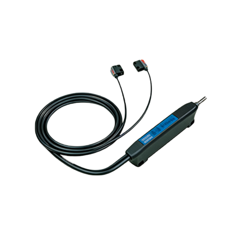
Standard Voltage Ranges for Common Sensor Types
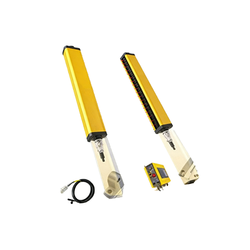
For off-the-shelf photoelectric sensors used in automation, the voltage is clearly specified in the datasheet. Diffuse, retro-reflective, and through-beam sensors typically require 12-24 VDC. Within this range, the sensor's output switching circuit (e.g., NPN/PNP transistor) functions correctly. If the voltage is too low, the sensor may not trigger reliably; if too high, it risks damage. For experimental setups using basic components, an infrared LED emitter often needs 1.2-1.7 V forward voltage at 20-50 mA current, which is usually provided via a current-limiting resistor from a 5V or 12V supply. The photodetector side (e.g., phototransistor) typically operates with a collector-emitter voltage supplied from the same 5-12V circuit.
Factors Influencing Voltage Selection in Experiments
Several key factors determine the optimal voltage in a photoelectric sensor experiment. First, consider the sensing distance: longer ranges may require higher emitter current (and thus a higher supply voltage to overcome circuit losses). Second, the response speed needed: higher voltage can sometimes enable faster switching in the detector circuit, but staying within the component's absolute maximum rating is critical. Third, ambient light conditions: in high-ambient-light experiments, a modulated light source might be used, which can involve specific voltage requirements for the modulation circuit. Always consult component datasheets for absolute maximum ratings and typical operating conditions.
Power Supply Considerations and Circuit Design
A stable, regulated DC power supply is essential for reproducible experiments. Voltage ripple should be minimized, as it can cause erratic sensor behavior. For prototype circuits, using a bench power supply with adjustable voltage and current limit is ideal. When integrating the sensor with a microcontroller (e.g., Arduino, Raspberry Pi), ensure voltage level compatibility. Many sensor modules include voltage regulation and output conditioning, allowing them to be powered by a wide range (e.g., 5-24 VDC) while providing a 3.3V or 5V logic output. Always include protective components like reverse-polarity diodes or fuses if the sensor is connected to an industrial power source during testing.
Experimental Procedure for Determining Optimal Voltage
To empirically determine the required voltage for a specific experimental setup, follow a systematic approach. Begin by powering the sensor or emitter circuit at the minimum recommended voltage. Gradually increase the voltage while monitoring the sensor's output response to a test object. Use an oscilloscope or multimeter to observe the output signal stability and switching points. Record the voltage at which reliable operation begins and note any changes in sensing range or response time. Continue increasing voltage until no further performance improvement is observed, but stop well before reaching the maximum rated voltage. This process helps identify the most efficient operating point for your particular application.
Safety and Best Practices
Always prioritize electrical safety when conducting experiments. Even at low voltages, ensure proper insulation and avoid short circuits. For sensors connected to higher industrial voltages (e.g., 24 VDC), use appropriate connectors and enclosures. Implement current limiting to protect LED emitters from overcurrent, which can be achieved with series resistors or constant current drivers. When experimenting with laser-based photoelectric sensors, adhere to laser safety classifications and avoid direct eye exposure. Document all voltage settings, component values, and observations meticulously to ensure experiment repeatability and troubleshooting efficiency.