Introduction to Photoelectric Sensors in Sealing Machines
Photoelectric sensors are critical components in modern sealing machines, providing precise detection and control for packaging processes. These sensors operate by emitting a light beam—typically infrared or visible light—and detecting changes in the received light intensity caused by objects interrupting the beam. In sealing applications, they ensure accurate positioning of packages, monitor material presence, and trigger sealing actions, thereby enhancing efficiency and reducing waste. Understanding their wiring is essential for proper installation, troubleshooting, and maintenance, which directly impacts machine reliability and safety. This article details the standard wiring configurations for common photoelectric sensors used in sealing equipment, focusing on practical implementation and industry best practices.
Types of Photoelectric Sensors and Their Functions
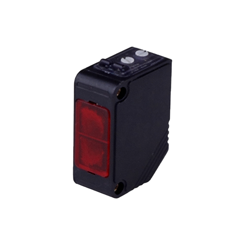
Sealing machines commonly employ three main types of photoelectric sensors: through-beam, retro-reflective, and diffuse reflective. Through-beam sensors consist of separate emitter and receiver units, offering long-range detection and high accuracy, ideal for detecting transparent or thin materials. Retro-reflective sensors use a single unit with a reflector, suitable for medium-range applications where object color or reflectivity may vary. Diffuse reflective sensors detect objects by reflecting light off the surface, making them versatile for close-range tasks like package alignment. Each type has specific wiring requirements based on its output configuration—such as NPN (sinking) or PNP (sourcing)—and voltage ratings (typically 12-24V DC). Selecting the correct sensor type depends on factors like detection distance, environmental conditions, and the sealing machine's control system.
Standard Wiring Diagram Components and Symbols
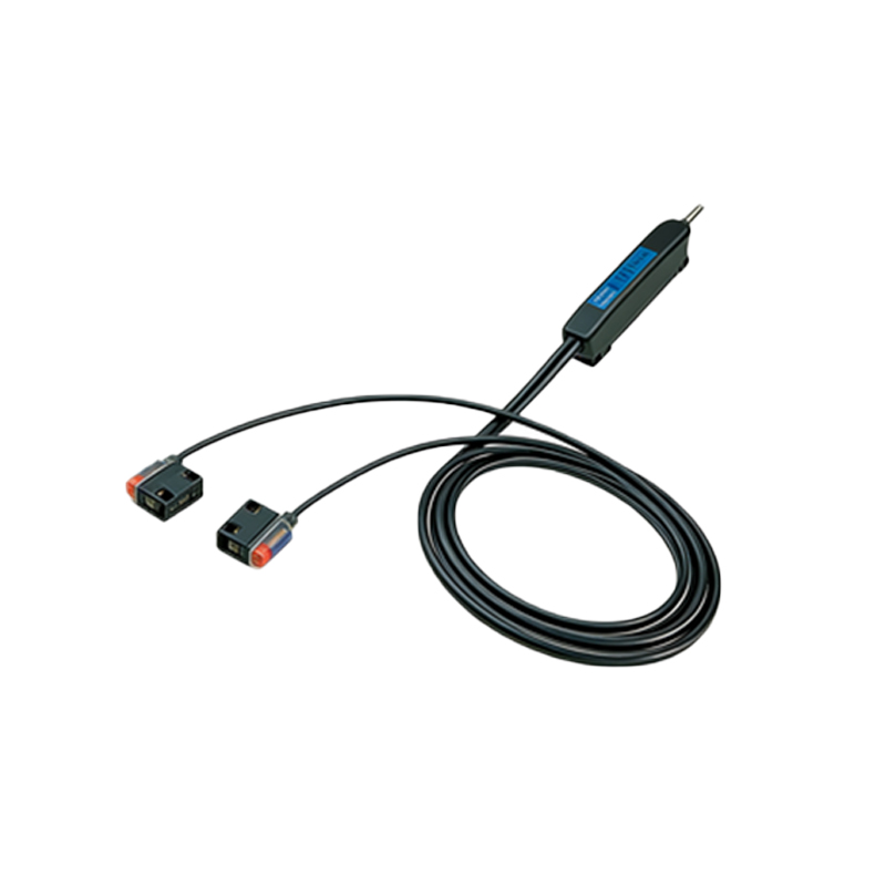
A typical photoelectric sensor wiring diagram includes several key components: the sensor itself, power supply, load (e.g., relay, PLC input), and protective devices like fuses. Symbols are standardized: a circle or rectangle represents the sensor, with labeled terminals for power (V+ or brown wire), ground (0V or blue wire), and output (black wire for NPN/PNP). Outputs may be normally open (NO) or normally closed (NC), affecting circuit behavior when an object is detected. Diagrams often indicate wire colors per international standards (IEC or JIS), such as brown for positive, blue for negative, and black for output. Additional features like timing functions or diagnostic LEDs are shown with specific symbols. Understanding these elements helps technicians interpret diagrams quickly, ensuring correct connections and minimizing errors during installation.
Step-by-Step Wiring Procedure for NPN and PNP Sensors
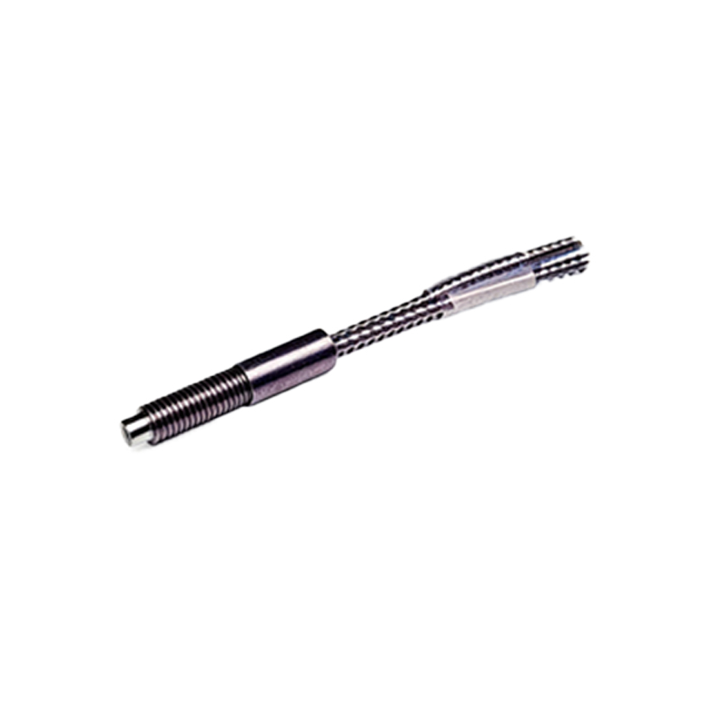
Wiring photoelectric sensors involves connecting power and output circuits based on the sensor type. For NPN sensors, the output acts as a sinking device: connect the brown wire to the positive DC supply (e.g., +24V), the blue wire to the negative (0V), and the black output wire to the load, which then links to the positive supply. When activated, the sensor connects the output to ground, completing the circuit. For PNP sensors, the output sources current: wire the brown and blue wires similarly, but connect the black output directly to the load, with the load's other side tied to ground. Always verify voltage ratings (e.g., 10-30V DC) and current limits to prevent damage. Use shielded cables in noisy environments, and ground the shield at one end to reduce interference. Test connections with a multimeter before powering the sealing machine to ensure proper polarity and continuity.
Integration with Sealing Machine Control Systems
In sealing machines, photoelectric sensors interface with programmable logic controllers (PLCs), relays, or motor drives to automate operations. Wiring integration involves connecting the sensor output to a PLC input module: for NPN sensors, use a sinking input card; for PNP, use a sourcing card. Ensure compatibility by checking the PLC's specifications, such as input impedance and voltage thresholds. For relay-based controls, wire the sensor output to the relay coil, with protective diodes for DC coils to suppress voltage spikes. In advanced systems, sensors may communicate via IO-Link or Ethernet for real-time diagnostics. Proper integration includes setting parameters like response time and sensitivity via potentiometers or software, aligning with the sealing cycle's speed—for instance, adjusting detection delay to match conveyor belt movements. Document all connections in a wiring schematic for future reference.
Common Wiring Issues and Troubleshooting Tips
Faulty wiring can lead to sensor malfunctions, causing sealing errors or machine downtime. Common issues include incorrect power polarity, loose connections, or short circuits. Symptoms may involve no output signal, erratic detection, or sensor damage. To troubleshoot, first inspect physical connections for tightness and corrosion. Use a voltmeter to check power supply voltage at the sensor terminals—it should match the rated value (e.g., 24V ±10%). Verify output activity by observing the sensor's LED indicator when an object is present; if it lights but no signal reaches the controller, test the output wire for continuity. Ensure the load impedance is within limits; too high a load can reduce signal strength. In noisy industrial settings, electromagnetic interference may disrupt signals—add ferrite cores or relocate wiring away from motors and high-voltage cables. Regularly clean sensor lenses to maintain accuracy, and follow manufacturer guidelines for maintenance intervals.
Safety and Maintenance Best Practices
Safe wiring practices are paramount to prevent electrical hazards and ensure sealing machine longevity. Always disconnect power before wiring or modifying connections. Use appropriately rated wires (e.g., 18-22 AWG for low-voltage DC) and secure them with cable glands or conduits to avoid strain. Implement overcurrent protection with fuses or circuit breakers, sized per the sensor's specifications. For maintenance, schedule periodic inspections of wiring integrity, checking for wear, heat damage, or moisture ingress. Calibrate sensors annually to account for environmental changes like temperature fluctuations. Train personnel on lockout-tagout procedures and diagram interpretation. Adhering to standards such as ISO 13849 for safety-related controls reduces risks. By prioritizing safety and proactive maintenance, operators can enhance sensor reliability and extend the sealing machine's operational life, supporting efficient packaging workflows.