Introduction to Turck Photoelectric Sensors
Turck photoelectric sensors are renowned for their reliability and versatility in industrial automation. These sensors operate by emitting a light beam, typically infrared, visible red, or laser, and detecting changes in the received light to sense the presence, absence, or distance of an object. Understanding the correct wiring is fundamental to ensuring optimal performance, safety, and integration into control systems. This guide provides a detailed overview of standard wiring configurations for common Turck photoelectric sensor models, focusing on DC models which are prevalent in factory automation.
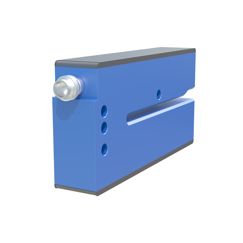
Understanding Sensor Output Types and Wiring Basics
Before examining specific diagrams, it is crucial to identify the sensor's output type, as this dictates the wiring scheme. Turck photoelectric sensors primarily feature three output configurations: PNP (sourcing), NPN (sinking), and Push-Pull (complementary). A PNP sensor switches the positive voltage to the load, while an NPN sensor switches the negative or ground side. Push-Pull outputs incorporate both PNP and NPN transistors, allowing connection to both sourcing and sinking inputs. Always verify the output type marked on the sensor label or datasheet. The fundamental components of a standard 3-wire DC sensor are: Brown wire for DC+ (positive supply), Blue wire for DC- (ground or common), and a Black wire (or sometimes white, depending on model) for the switched output signal.
Standard 3-Wire DC PNP (Sourcing) Wiring Diagram
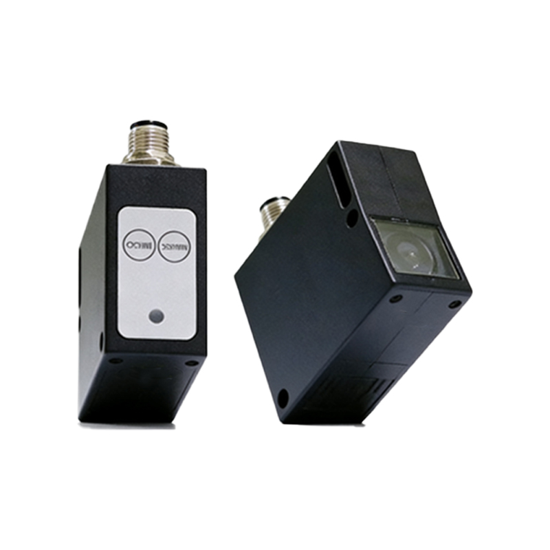
For a typical 3-wire DC PNP sensor, the wiring connects directly to a programmable logic controller (PLC) digital input or a relay. Connect the brown wire to the positive terminal of your DC power supply (e.g., +24V DC). Connect the blue wire to the negative terminal (0V DC) of the same supply. The black output wire is connected to the PLC's input channel. The corresponding common terminal of that PLC input module must be connected to the DC- (0V). In this configuration, when the sensor detects an object, it sources current from the +24V supply through the black wire to the PLC input, creating a "high" signal. Ensure the supply voltage matches the sensor's rated voltage range.
Standard 3-Wire DC NPN (Sinking) Wiring Diagram
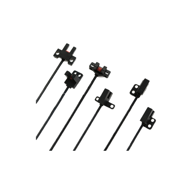
The wiring for a 3-wire DC NPN sensor is similar but with a key difference in the current path. Again, connect the brown wire to DC+ and the blue wire to DC-. The black output wire is connected to the PLC input. However, for an NPN sensor, the common terminal of the PLC input module must be connected to the DC+ (+24V). When the sensor activates, it sinks current from the PLC input, through the black wire, to the DC- (0V), creating a "low" signal at the PLC. It is vital to match the PLC input type (sinking or sourcing) with the sensor output type to form a complete circuit.
Wiring for 4-Wire Sensors and Dual Outputs
Some Turck sensors feature a fourth wire, often providing a complementary output (e.g., NO and NC) or a separate output for a specific function like a teach-in signal or a short-circuit protected output. For a sensor with dual PNP outputs (e.g., one Normally Open and one Normally Closed), you will typically find wires: Brown (DC+), Blue (DC-), Black (NO output), and White (NC output). Each output wire is connected to a separate PLC input channel. The wiring principles remain the same: maintain correct polarity for power and ensure the PLC input commons are wired appropriately for the output type. Always consult the specific sensor's datasheet for the exact pinout and wire color codes.
Connecting to Loads and Relay Interfaces
When interfacing directly with a relay or a lamp, the wiring must account for the load's current draw. For a PNP sensor driving a relay coil, connect one side of the coil to DC+, and the other side to the sensor's black output wire. The sensor's blue and brown wires connect to the power supply as usual. When active, the sensor completes the circuit, energizing the coil. A freewheeling diode across the relay coil is recommended to suppress voltage spikes. Ensure the relay coil's operating voltage matches the sensor supply and that the sensor's maximum switching current is not exceeded.
Key Considerations for Installation and Troubleshooting
Proper installation extends beyond correct wiring. Use shielded cables in electrically noisy environments, connecting the shield to ground at one end only. Maintain adequate separation from power cables to prevent inductive coupling. For troubleshooting, a multimeter is essential. Check for the correct supply voltage between brown and blue wires. With power applied and no target present, measure the voltage between the output wire (black) and blue wire. For a PNP sensor, you should read near 0V (OFF state); for an NPN, you should read near supply voltage. When a target is presented, the voltage should switch. Incorrect wiring often leads to a sensor that is permanently ON or OFF.
Conclusion and Best Practices
Correctly wiring your Turck photoelectric sensor is a critical step for reliable operation. Always start by identifying the sensor model and its output specification from the product label or documentation. Use the correct wire colors as a guide, but verify with a datasheet as colors can vary by product line. Double-check all connections against your system's requirements—whether connecting to a PLC, relay, or other controller. Adhering to these wiring principles and installation best practices will ensure your sensors provide accurate, long-lasting service in demanding industrial environments.