Understanding Photoelectric Sensor Wiring Fundamentals
Before initiating any wiring replacement, it is crucial to comprehend the basic electrical configuration of a typical industrial photoelectric sensor. Most sensors operate on a DC voltage supply, commonly 12-24V DC, though some models use AC. The standard wiring involves three or four wires: a brown wire for positive voltage supply (V+), a blue wire for the common negative or 0V (V-), a black wire for the output signal (often NPN or PNP switching), and sometimes a white wire for a second output or function. The core principle is that the sensor's internal circuitry, powered by V+ and V-, uses a light emitter and receiver to detect objects. Upon detection, it switches the state of the output wire, sending a signal to a controller like a PLC. Miswiring can lead to sensor failure, damaged equipment, or safety hazards. Always consult the specific sensor's datasheet for its exact pinout and electrical characteristics, as colors and functions can vary by manufacturer and model (e.g., diffuse, retro-reflective, or through-beam types).
Essential Safety Precautions and Preparation
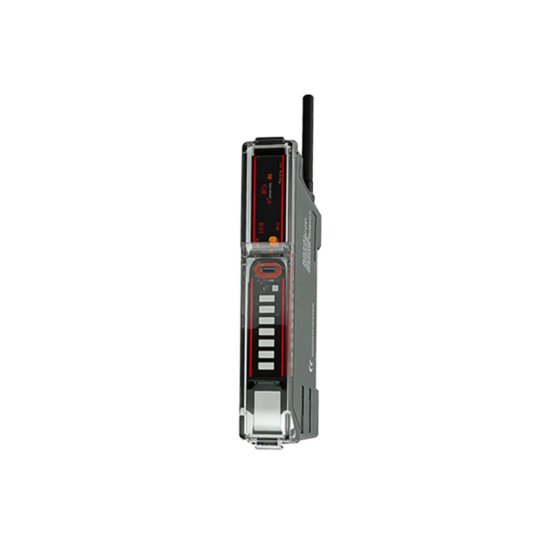
Safety is the absolute priority when working with industrial electrical components. Begin by following Lockout/Tagout (LOTO) procedures to de-energize the entire circuit or machine. Verify the absence of voltage at the sensor connection point using a properly rated multimeter. Gather the necessary tools: wire strippers, crimping tools, appropriate terminals (e.g., ferrule connectors), a screwdriver set, and the correct gauge of replacement cable. The replacement cable should match or exceed the original's specifications for voltage rating, current capacity, insulation type (e.g., for oil or chemical resistance), and strand count. It is advisable to have the sensor's manual or wiring diagram on hand. Label all existing wires before disconnection if the system is complex. This step prevents errors during reconnection and ensures system integrity upon restart.
Step-by-Step Wire Replacement Procedure
First, after confirming zero energy, carefully disconnect the old wiring from the sensor's terminal block or connector. Note the position of each wire. If the sensor uses a quick-disconnect M12 or M8 connector, simply unplug it. For hard-wired sensors, loosen the terminal screws and remove the wires. Next, prepare the new cable. Strip a consistent length of insulation from each conductor, typically 7-10mm, ensuring no strands are cut. Crimp the correct ferrule or terminal onto each stripped end. This provides a secure, reliable connection and prevents stray strands from causing shorts. Insert each wire into its designated terminal on the sensor according to your earlier notes or the datasheet: brown to V+, blue to V-, black to output. Tighten the terminal screws firmly to the manufacturer's specified torque to ensure good electrical contact without damaging the conductor. For connectorized sensors, mate the new cable's plug securely with the sensor's socket until it clicks.
Post-Installation Testing and Verification
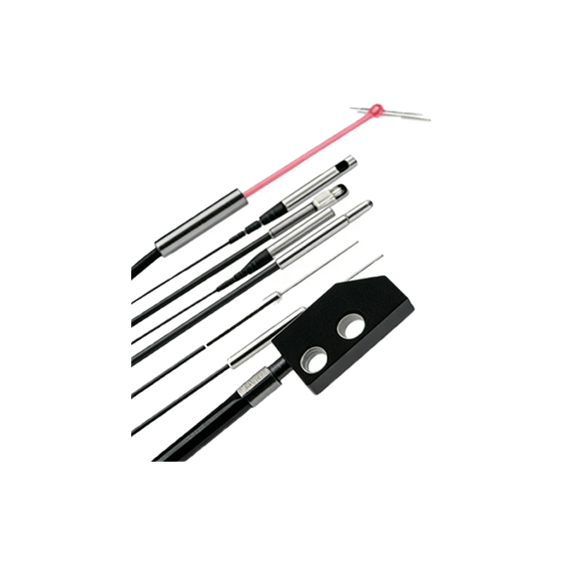
Do not re-energize the system immediately after wiring. First, perform a visual and mechanical inspection. Ensure no exposed copper is visible outside the terminals, all connections are tight, and the cable strain relief (if present) is properly secured. Check that the cable routing avoids sharp edges, moving parts, or high-temperature areas. Once satisfied, apply power to the system. Observe the sensor's indicator LEDs. Most sensors have a power (green) LED and a switching (yellow or orange) LED. A steady green light indicates correct power supply wiring. To test functionality, introduce a target object into the sensor's sensing range. The output LED should illuminate or change state, confirming the switching action. Finally, use a multimeter to measure the voltage between the output wire (black) and common (blue). It should change from a high state (e.g., 24V) to a low state (near 0V), or vice-versa, depending on the sensor's logic (NO/NC), when the target is detected. This verifies the electrical signal is being generated correctly.
Troubleshooting Common Wiring Issues
If the sensor fails to operate after replacement, methodically troubleshoot. If the power LED is off, re-check the supply wiring (brown/blue) for correct polarity and voltage. An inverted polarity can damage some sensors. If the power LED is on but there is no output response, verify the output wire (black) connection and its configuration. Ensure the load (e.g., PLC input) is correctly connected between the output and V+ (for PNP) or V- (for NPN). A frequent error is mismatching the sensor's output type (PNP sourcing vs. NPN sinking) with the controller's input requirements. Intermittent operation may point to a loose terminal screw or a damaged wire strand. Electrical noise interference, often from running sensor cables parallel to high-power lines, can cause erratic behavior. Re-route cables separately or use shielded cable, properly grounding the shield at one end only. Always double-check against the wiring diagram.