Introduction to DC Sinking Outputs
In industrial automation, photoelectric sensors are fundamental components for detecting the presence, absence, or position of objects without physical contact. Among their various output configurations, the DC sinking output, commonly referred to as an NPN output, is a prevalent and critical design. This configuration is defined by the type of transistor used in the output stage—an NPN bipolar junction transistor. The terminology "sinking" precisely describes its operational role: when activated, the output transistor connects the load to the common ground (0V), effectively "sinking" current from the load into the sensor. Understanding this mechanism is essential for proper integration with programmable logic controllers (PLCs), counters, and other control system inputs to ensure reliable and safe circuit operation.
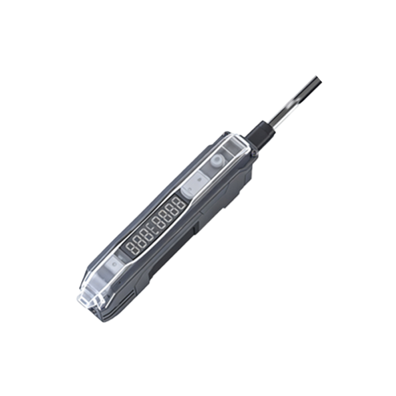
Internal Circuitry and Operating Principle
The core of a DC sinking output sensor is an NPN transistor. Internally, the collector of this transistor is connected to the sensor's output terminal (often labeled as the black wire in a standard 3-wire DC sensor). The emitter is connected to the sensor's negative supply terminal (0V or common). The base is driven by the sensor's internal detection circuit. When no target is detected, the transistor is in an "off" state, presenting a high impedance between the output and common. No current flows. Upon target detection, the internal circuit applies a signal to the transistor's base, turning it "on." This creates a low-impedance path from the output terminal to the 0V common. In a typical wiring scheme, one side of the external load (e.g., a PLC digital input) is connected to a positive voltage supply (+V), and the other side is connected to the sensor's output terminal. When the sensor activates, current flows from the +V supply, through the load, into the sensor's output terminal, and is sunk to ground through the conducting NPN transistor, thereby completing the circuit and signaling the detection event.
Wiring Configuration and Load Connection
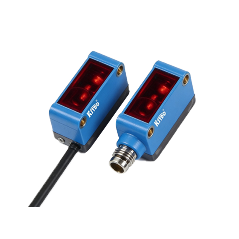
Correct wiring is paramount for the functionality of sinking output sensors. A standard three-wire DC sensor comprises a brown wire (+V supply), a blue wire (0V common), and a black wire (output signal). For a sinking (NPN) output, the load must be connected between the positive supply and the black output wire. A typical connection to a PLC digital input module would be: the brown wire to the DC positive terminal, the blue wire to the DC common/0V terminal, and the black output wire to the PLC's input point. The PLC input point itself is internally connected to its own positive supply through a pull-up resistor or similar circuitry. When the sensor is off, the PLC input sees a high voltage (near +V). When the sensor turns on, it pulls the PLC input voltage down to near 0V, registering as an "ON" or "TRUE" state. This "active-low" behavior is a hallmark of sinking outputs and must be correctly configured in the PLC's input settings.
Comparison with Sourcing (PNP) Outputs
The complementary configuration to sinking is the sourcing, or PNP, output. This distinction is a primary source of confusion and wiring errors. A PNP output uses a PNP transistor, where the emitter is connected to +V and the output (from the collector) provides a positive voltage to the load when active. In simple terms, a sinking (NPN) output provides a path to ground for current, while a sourcing (PNP) output provides a path from the positive supply. The choice between NPN and PNP often depends on regional conventions, the design of the control system's input cards, and safety considerations. Many modern PLCs offer input cards that can be configured for either type, but understanding the sensor's specification is crucial to prevent damage or malfunction.
Advantages and Application Considerations
Sinking outputs offer several advantages in specific applications. They are traditionally common in systems designed with positive logic, where an active-low signal is standard. From a safety perspective, in some fault conditions, a sinking output that fails shorted may pull a signal to ground, which can be designed to trigger a safe state in the machinery. Furthermore, when interfacing with certain types of electronic circuits or microcontrollers that require current sinking capability, NPN outputs are the natural choice. Key application considerations include ensuring the load's voltage and current ratings are compatible with the sensor's output specifications, verifying the PLC input type, and paying close attention to the common grounding of the sensor and the control system to avoid ground loops or noise issues.
Troubleshooting Common Issues
Several common problems can arise with DC sinking output sensors. If the sensor does not trigger the load, verify the wiring: ensure the load is connected between +V and the sensor's output, not between the output and ground. Confirm the power supply polarity is correct. Use a multimeter to check the voltage at the output wire relative to common; it should be near supply voltage when inactive and drop to near 0V when active. If the output seems stuck low, there may be an internal failure of the transistor or a wiring short to ground. Conversely, if stuck high, the transistor may be open or the internal detection circuit may have failed. Always consult the sensor's datasheet for specific diagnostic LED indicators and output characteristics. Ensuring a clean, stable power supply and proper shielding in electrically noisy environments is also critical for reliable operation.