Understanding the Proximity Sensor System in Modern Land Rovers
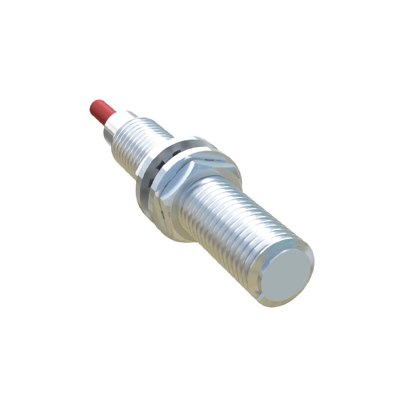
Modern Land Rover vehicles are equipped with a sophisticated network of proximity sensors, integral to the Parking Aid and Advanced Driver Assistance Systems (ADAS). These sensors, typically ultrasonic, are strategically placed around the vehicle's bumper fascias. The left rear sensor plays a critical role in detecting obstacles during reversing maneuvers and is a key component for features like Park Assist and Cross Traffic Alert. This sensor is part of a closed-loop circuit, receiving a regulated voltage supply, often 12V, from the vehicle's Body Control Module (BCM) or a dedicated parking aid module. It communicates back to the module via a signal return line. Any compromise in this circuit's integrity, particularly a short to the vehicle's power or ground, can lead to significant electrical faults.
Root Causes of a Battery Short Circuit via the Sensor
A direct battery short through a proximity sensor is a severe fault, often resulting in blown fuses, damaged wiring, or module failure. The primary cause is physical damage to the sensor or its wiring harness. Impact from minor collisions, debris strikes, or improper repair work can crush the wiring, stripping insulation and allowing the positive supply wire to contact the vehicle's chassis (ground) or a constant battery feed. Corrosion is another major culprit, especially in the left rear quarter where water, salt, and road grime can accumulate. Corrosion can bridge the terminals inside the sensor connector or degrade wire insulation, creating a path to ground. In rare cases, an internal failure within the sensor itself can cause a short circuit between its power and ground terminals.
Symptom Identification and Diagnostic Procedures
The most immediate symptom is the illumination of multiple warning lights on the instrument cluster, including the battery warning light, parking aid fault message, and potentially other ADAS alerts. The vehicle may log diagnostic trouble codes (DTCs) such as "B1B96-87 Left Rear Outer Parking Aid Sensor - Circuit Short to Battery" or "U codes" indicating communication loss with the sensor module. A key diagnostic step is to check the relevant fuse, usually in the rear junction box or passenger compartment fuse panel, which will likely be blown. Using a multimeter, technicians should first disconnect the sensor and measure resistance between the power pin and ground. A reading near zero ohms confirms a short. A visual inspection of the wiring loom from the sensor back to the module, focusing on areas of flex and potential pinch points, is essential.
Step-by-Step Repair and Replacement Protocol
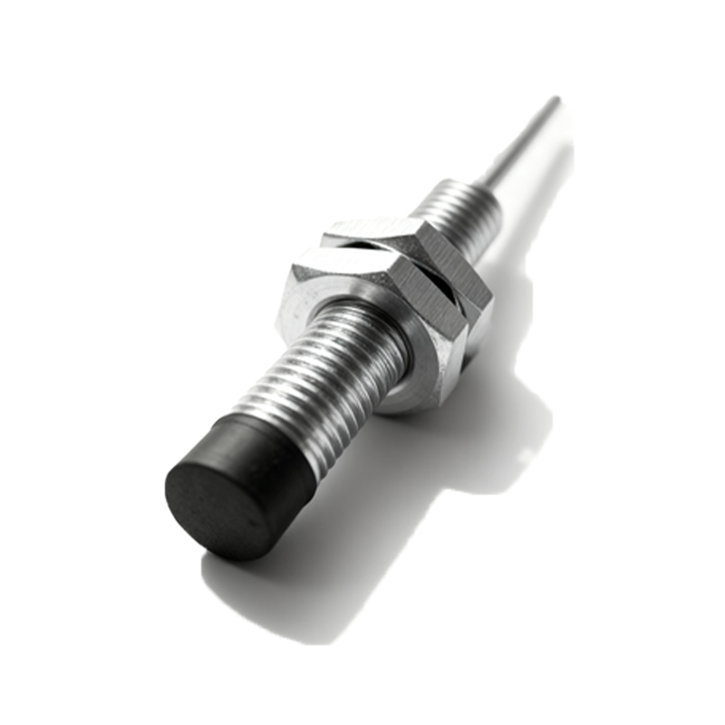
Upon identifying the faulty component or wiring section, a systematic repair is required. First, disconnect the vehicle battery to prevent further electrical damage. If the wiring harness is damaged, it must be repaired using solder and heat-shrink tubing or replaced with a OEM-grade repair section—never use simple twist connectors. The sensor itself is not serviceable and must be replaced as a unit. When installing a new Land Rover proximity sensor, it is crucial to use the correct part number, as frequencies and calibrations vary. After physical replacement, all associated modules, particularly the BCM or Parking Aid Module, may require configuration and calibration using Land Rover's approved diagnostic software (SDD or Pathfinder). This ensures the sensor's output is correctly interpreted by the vehicle's systems.
Preventive Measures and Best Practices
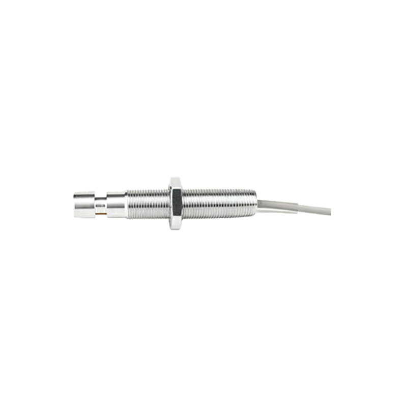
Preventing recurrence involves addressing environmental and mechanical stressors. Ensure all bumper mounts and shields are correctly installed to protect the sensor wiring. Regularly wash the vehicle's underbody and rear bumper area to remove corrosive agents. During any repair or modification work near the rear bumper, technicians must take care not to pinch or reroute wiring incorrectly. Using dielectric grease in the sensor electrical connector can help mitigate moisture ingress and corrosion. Furthermore, adhering to manufacturer-recommended diagnostic procedures instead of guesswork prevents misdiagnosis and protects other expensive control modules from potential voltage spikes caused by the short circuit.