Introduction to Photoelectric Sensors
Photoelectric sensors are indispensable components in modern industrial automation, serving as the "eyes" of a control system. These devices operate by emitting a beam of light, typically infrared, visible red, or laser, and detecting changes in the received light signal. The fundamental principle involves the interruption, reflection, or modulation of this light beam by a target object. Common types include through-beam, retro-reflective, and diffuse reflective sensors, each suited for specific detection ranges, environmental conditions, and object properties. Their non-contact nature, high speed, and reliability make them ideal for tasks like object counting, positioning, edge detection, and level control across diverse industries, from packaging and material handling to automotive assembly lines.
Integration with PLC Hardware
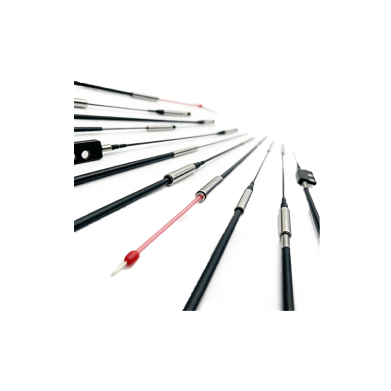
Connecting a photoelectric sensor to a Programmable Logic Controller (PLC) is a foundational step. Most industrial photoelectric sensors provide discrete digital outputs, either PNP (sourcing) or NPN (sinking), which interface directly with a PLC's digital input module. The sensor's output switches state (e.g., from OFF to ON) when an object is detected, sending a corresponding voltage signal to the PLC input point. Proper wiring is critical: ensuring correct polarity, common voltage levels, and the use of shielded cables in electrically noisy environments. For analog sensors that measure distance or intensity, a PLC's analog input module is required. Additionally, modern sensors with IO-Link or Ethernet/IP capabilities offer advanced diagnostics and parameter setting directly through the PLC network, simplifying integration and maintenance.
Basic PLC Ladder Logic Programming
The core of sensor integration lies in PLC programming, with Ladder Logic (LAD) being the most prevalent language. A basic detection program starts by assigning the sensor's physical input (e.g., I0.0) to a memory bit or tag. A standard normally open (NO) contact instruction referencing this input can then be used to trigger actions. For instance, when input I0.0 becomes TRUE (object detected), it can energize a coil controlling a conveyor motor (Q0.0), activate a timer, or increment a counter. It is essential to incorporate debounce logic, often using timers, to filter out mechanical vibration or electrical noise that might cause false triggering. Simple programs might use the sensor input to latch an alarm condition or initiate a sequential process step within the PLC's scan cycle.
Implementing Advanced Control Logic
Beyond simple on/off control, photoelectric sensors enable sophisticated automation sequences. For precise positioning, a sensor can trigger high-speed counter inputs on the PLC to measure encoder pulses, calculating exact object position. In batching systems, multiple sensors can be programmed to work in concert; for example, one sensor detects a product arrival, triggering a timer delay before a second sensor verifies correct placement, with the PLC evaluating both signals before allowing a robotic arm to proceed. State machine programming or sequential function chart (SFC) methods are highly effective for these multi-step processes. Furthermore, comparing sensor signals against setpoints allows for quality control, such as rejecting items that break a light beam for too short or too long a duration, indicating a size defect.
Diagnostics and Error Handling
Robust PLC programs must include comprehensive diagnostic routines for sensor health. Many sensors provide built-in diagnostic outputs (like a separate wire for alignment status or contamination warning) that can be wired to separate PLC inputs. The program can monitor these signals and trigger maintenance alerts. Software diagnostics involve programming "watchdog" timers: if a sensor expected to detect an object at regular intervals fails to do so within a set time, the PLC can flag a jam or sensor fault, safely stopping the machine. Implementing first-in-first-out (FIFO) buffer logic with sensor inputs can help trace the root cause of a fault in a fast-moving line. Regular checks of sensor response time within the PLC program can also predict lens fouling or LED degradation.
Optimization and Best Practices
Optimizing the interplay between sensor and PLC enhances system performance and reliability. Key practices include selecting the correct sensor type for the application to ensure a strong, stable signal, minimizing the need for complex signal filtering in the PLC. Programming should utilize positive logic for clarity and employ consistent naming conventions for sensor-related tags (e.g., "PhotoSen_Entry_OK"). Response time should be considered; the PLC scan time must be faster than the rate of sensor state changes. For high-speed counting, using dedicated hardware counters within the PLC CPU is preferable to software counters. Finally, thorough simulation and testing of the PLC logic with simulated sensor inputs are crucial before commissioning, ensuring all interlocks and sequences function as designed under normal and fault conditions.