Introduction to Capacitive Proximity Sensors
Capacitive proximity sensors are widely used in industrial automation for detecting both metallic and non-metallic objects without physical contact. These sensors operate based on the principle of capacitance change. When an object enters the sensing field, it alters the dielectric constant between the sensor's electrodes, leading to a measurable change in capacitance. This change triggers the sensor's output signal, enabling detection. Unlike inductive sensors, capacitive variants can sense materials such as plastics, liquids, and granular substances, making them versatile in diverse applications like level detection, material handling, and assembly line monitoring. Their ability to function through non-metallic barriers further expands their utility in packaging and container industries.
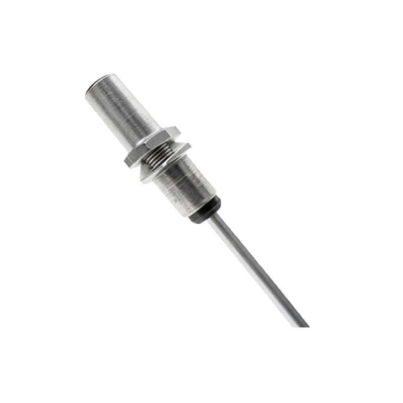
Key Components and Structural Layout
The structure of a capacitive proximity sensor comprises several integral components arranged to optimize sensitivity and reliability. At the core is the sensing electrode, typically a conductive plate or surface that generates an electrostatic field. This electrode is connected to an oscillator circuit that produces a high-frequency signal. Surrounding the electrode is a guard ring or shield, which focuses the sensing field and minimizes interference from surrounding objects. The housing, often made of durable plastics or metals, protects internal electronics from environmental factors like dust, moisture, and mechanical impact. Internally, a demodulator circuit converts capacitance changes into electrical signals, while an output stage (e.g., transistor or relay) interfaces with control systems. A diagram would illustrate these elements layered to show how the electrode emits a field, the shield directs it, and the housing encapsulates the assembly.
Detailed Breakdown of the Sensing Electrode
The sensing electrode is the primary component responsible for detection. In structural diagrams, it appears as a flat or curved conductive surface, often circular or rectangular, positioned at the sensor's front face. This electrode is energized by the oscillator, creating an alternating electric field that extends into the surrounding space. When an object enters this field, it acts as a dielectric, increasing the effective capacitance between the electrode and ground. The electrode's design—such as its size, shape, and material—directly influences the sensing range and sensitivity. For instance, larger electrodes can detect objects from greater distances, while specialized coatings may enhance performance in humid conditions. Diagrams typically highlight the electrode's connection to the oscillator via conductive traces, emphasizing its role in field generation.
Role of the Oscillator and Signal Processing Circuitry
Adjacent to the sensing electrode in structural diagrams is the oscillator circuit, which generates a constant high-frequency signal (usually in the range of 100 kHz to 1 MHz). This signal energizes the electrode, maintaining the electrostatic field. As capacitance changes due to object proximity, the oscillator's frequency or amplitude shifts. This alteration is detected by a demodulator or comparator circuit, which processes the raw signal into a usable form. The circuitry often includes adjustable sensitivity controls, allowing users to fine-tune detection thresholds for specific materials or environments. In diagrams, these components are depicted as integrated circuits or discrete elements linked by pathways, showing how the oscillator feeds into signal conditioning modules before reaching the output stage.
Shielding and Housing Design Considerations
A critical aspect shown in capacitive proximity sensor diagrams is the shielding mechanism. The guard ring or shield, typically a conductive ring surrounding the sensing electrode, confines the electric field to a directed front-facing area. This prevents false triggers from objects approaching from the sides or rear, enhancing accuracy. The housing, illustrated as an outer shell, provides mechanical protection and environmental sealing. Materials like PTFE or stainless steel are common for housings in harsh industrial settings. Diagrams often use cross-sectional views to display how the shield is insulated from the electrode and grounded, while the housing incorporates mounting threads or brackets for installation. Proper design ensures compliance with IP ratings for dust and water resistance.
Output Configuration and Integration with Systems
The output stage of a capacitive proximity sensor is depicted in structural diagrams as a terminal block or connector linked to the processing circuitry. Common output types include NPN/PNP transistors for DC sensors or relay contacts for AC variants, providing switching signals to programmable logic controllers (PLCs) or other automation devices. Diagrams show wiring schematics, indicating power supply connections (e.g., 10-30 V DC) and load connections. Some sensors feature LED indicators for status monitoring, illustrated as small lights on the housing. Integration aspects, such as cable glands or quick-disconnect fittings, are also highlighted to demonstrate ease of installation in control panels or machinery.
Applications and Practical Insights from the Structure
Analyzing the structural diagram reveals why capacitive proximity sensors excel in real-world applications. For example, in liquid level detection, the sensor's ability to sense through