Introduction to Photoelectric Sensor Symbols
Photoelectric sensors are essential components in industrial automation, used for detecting the presence, absence, or position of objects. To ensure proper installation, operation, and maintenance, manufacturers imprint various symbols and markings on these devices. These symbols convey critical information about the sensor's specifications, electrical characteristics, environmental ratings, and safety features. Understanding these markings is crucial for engineers and technicians to select the right sensor for an application and integrate it correctly into a control system. This article decodes common symbols found on photoelectric sensors, providing a comprehensive guide for professionals in the electrical and automation industries.
Power Supply and Electrical Ratings
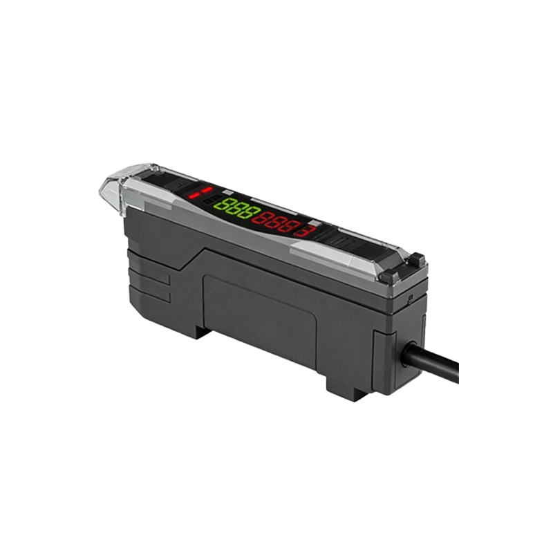
One of the most important sets of symbols on a photoelectric sensor relates to its power requirements and electrical ratings. Typically, you will find markings indicating the voltage range (e.g., 10-30 V DC) and current consumption. Symbols such as "DC" for direct current or "AC" for alternating current are often present, along with polarity indicators like "+" and "-" for DC sensors. Additionally, output configuration symbols—like NPN or PNP for switching outputs—are clearly marked. For instance, an arrow pointing outward from the sensor symbol might represent a PNP (sourcing) output, while an arrow pointing inward could indicate an NPN (sinking) output. These markings help prevent wiring errors that could lead to sensor damage or system malfunction.
Environmental Protection and Housing Ratings
Photoelectric sensors often operate in harsh industrial environments, so symbols denoting environmental protection are vital. The Ingress Protection (IP) rating is commonly displayed, such as IP67, which indicates dust-tight and waterproof capabilities. Symbols like a water droplet or dust cloud may accompany the IP code for quick visual reference. Additionally, markings for temperature ranges (e.g., -25°C to 55°C) ensure the sensor is suitable for specific climatic conditions. For sensors used in hazardous areas, certifications like ATEX or IECEx symbols appear, indicating compliance with explosion-proof standards. These symbols guide users in selecting sensors that can withstand their operational environment, enhancing reliability and safety.
Optical and Functional Indicators
Symbols related to the sensor's optical function and status indicators are also prominent. Many sensors feature LED indicators that show power status, output activation, or alignment quality. These are often represented by simple pictograms, such as a light bulb for power or an eye for detection. Additionally, symbols may indicate the sensing mode—like through-beam, retro-reflective, or diffuse—using diagrams of light paths. For example, two opposing arrows might represent through-beam sensors, while a single arrow with a reflector symbol could denote retro-reflective types. Understanding these symbols aids in quick setup and troubleshooting, ensuring optimal sensor performance in applications like conveyor systems or packaging machinery.
Mounting and Mechanical Specifications
Mechanical information is conveyed through symbols for mounting dimensions, alignment aids, and housing materials. Common markings include thread sizes (e.g., M18 or M30) for cylindrical sensors, along with diagrams showing mounting holes or brackets. Arrows or lines might indicate the sensing range or beam axis, helping with precise installation. Symbols for material composition, such as "SS" for stainless steel housing, are also found, which is crucial for corrosive environments. These markings ensure proper physical integration into machinery, reducing installation time and avoiding mechanical failures due to incorrect fitting or material incompatibility.
Safety and Compliance Markings
Safety is paramount in industrial settings, so photoelectric sensors carry symbols for regulatory compliance and safe usage. CE marking indicates conformity with European health and safety standards, while UL or CSA symbols show approval for North American markets. Warning symbols, like an exclamation point in a triangle, may highlight precautions such as avoiding direct eye exposure to the light beam. Additionally, symbols for electromagnetic compatibility (EMC) or RoHS (Restriction of Hazardous Substances) compliance are often present. These markings assure users that the sensor meets international safety and environmental regulations, minimizing risks in automated systems.
Conclusion and Best Practices
Deciphering the symbols on photoelectric sensors is key to leveraging their full potential in automation projects. Always refer to the manufacturer's datasheet for detailed explanations, as symbols can vary between brands. During installation, double-check power ratings and output configurations to prevent electrical issues. Consider environmental factors by verifying IP ratings and temperature limits. Regular maintenance, guided by status indicator symbols, can prolong sensor life and reduce downtime. By mastering these symbols, engineers can enhance system efficiency, ensure safety, and optimize performance across diverse industrial applications, from manufacturing to logistics.