Introduction to U-Shaped Photoelectric Sensors
A U-shaped photoelectric sensor, often referred to as a through-beam sensor, consists of two separate units: a light emitter and a light receiver, housed in a single, opposing U-shaped bracket. This configuration creates a consistent, uninterrupted light beam across the gap. When an object passes through this gap, it interrupts the beam, triggering a detection signal. The fundamental advantage of this design is its high reliability and long sensing distance relative to its size. Unlike diffuse or retro-reflective sensors, the U-shaped type is less susceptible to the object's color, reflectivity, or surface texture, making it ideal for precise object detection, counting, and positioning in automated machinery, packaging lines, and material handling systems.
Key Electrical Parameters
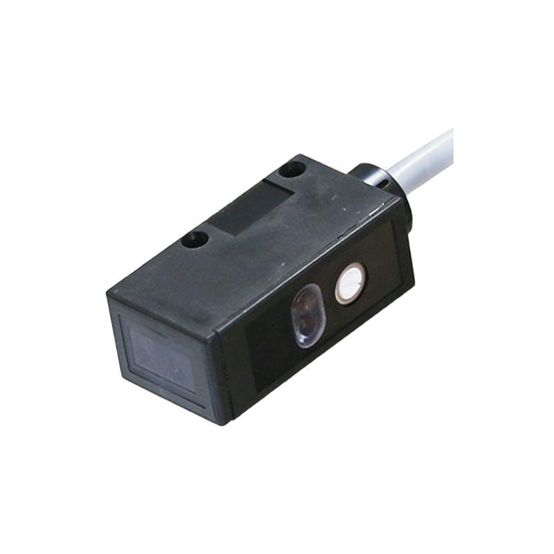
Understanding the electrical specifications is crucial for proper integration and safe operation. The operating voltage range, typically between 10-30V DC, defines the power supply compatibility. The current consumption, measured in milliamperes (mA), indicates the load on the power supply. The output configuration is a critical choice; it can be a transistor output (NPN or PNP, sinking or sourcing) or a relay contact. NPN (sinking) outputs are common, connecting the load to the positive voltage, while PNP (sourcing) outputs connect the load to ground. The load current rating specifies the maximum current the sensor's output can safely switch, which must not be exceeded by the connected device, such as a PLC input or a relay coil. Response time, measured in microseconds (µs) or milliseconds (ms), defines how quickly the sensor can react to a beam interruption and change its output state, a vital parameter for high-speed applications.
Optical and Mechanical Specifications
The sensing gap or slot width is the distance between the emitter and receiver arms. Selecting a gap slightly larger than the target object ensures reliable detection. The light source is typically a modulated infrared LED, though visible red or laser light sources are available for precise alignment or special applications. The modulated light helps the sensor ignore ambient light interference. The beam width or spot size at the receiver influences detection precision; a narrower beam allows for detecting smaller objects. The housing material, often made of ABS plastic or metal, provides environmental protection, with an IP (Ingress Protection) rating like IP67 indicating dust-tightness and protection against temporary immersion. The mechanical mounting style, including bracket types and screw sizes, must be considered for secure installation.
Environmental and Performance Parameters
Environmental conditions significantly impact sensor selection and longevity. The operating temperature range, for instance -25°C to +55°C, must encompass the ambient conditions of the application. Resistance to specific environmental factors like oil, chemicals, or washdown procedures may require specialized seals or housing materials. Another key performance parameter is the "light-on/dark-on" function. This allows the user to configure whether the output activates when the beam is received (light-on) or when it is interrupted (dark-on), providing flexibility for different control logic requirements. The presence of a sensitivity adjustment or stability indicator (often an LED) aids in fine-tuning and troubleshooting during setup.
Application-Specific Selection Criteria
Choosing the right U-shaped sensor involves matching its parameters to the application's demands. For high-speed counting on a conveyor, a fast response time and a suitable sensing gap are paramount. In dirty or dusty environments, a sensor with a high IP rating and a powerful modulated light source to penetrate contamination is necessary. For detecting small parts, the beam width and the precision of the gap become critical. If connecting to a programmable logic controller (PLC), ensuring the output type (NPN/PNP) matches the PLC input card is essential to avoid interface issues. Always consult the manufacturer's datasheet for detailed specifications, connection diagrams, and installation guidelines to ensure optimal and reliable performance in your specific industrial setting.