Understanding Photoelectric Sensor Wiring Fundamentals
Photoelectric sensors are indispensable components in modern industrial automation, converting light signals into electrical currents to detect objects. Their reliable operation hinges on correct wiring, which ensures accurate signal transmission and system integrity. A typical sensor consists of three core parts: the emitter, which projects a light beam; the receiver, which detects the light; and the control circuit, which processes the signal. Wiring connects these elements to a power source and a controller, such as a PLC. Incorrect wiring can lead to false triggers, sensor damage, or complete system failure. Therefore, grasping the basics—such as identifying wire colors, understanding voltage requirements, and recognizing output types—is the first step toward optimal performance. Most industrial sensors operate on DC voltages (10-30 VDC), though AC models exist. Always consult the datasheet before installation to match specifications.
Key Wiring Configurations: NPN vs. PNP and Output Types
The two primary wiring configurations are NPN (sinking) and PNP (sourcing), which define how the sensor interfaces with the control system. In an NPN setup, the output wire connects to the load, which is then linked to positive voltage; when activated, the sensor sinks current to ground, creating a low signal. This is common in Asian and European markets. Conversely, PNP wiring has the output connected to the load, which ties to ground; activation sources current from positive voltage, producing a high signal, prevalent in North America. Choosing between them depends on the PLC input type. Additionally, outputs can be normally open (NO) or normally closed (NC). An NO output closes the circuit upon detection, while an NC opens it. For example, in safety applications, an NC configuration may be preferred to fail-safe. Always verify compatibility with your control system to avoid malfunctions.
Step-by-Step Wiring Procedure for Industrial Applications
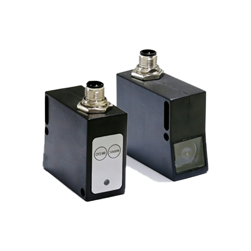
To wire a photoelectric sensor safely, follow a systematic approach. First, disconnect all power sources to prevent electrical hazards. Identify the wires: typically, brown is for positive voltage (V+), blue for negative or ground (V-), and black for the output signal (though colors can vary; white may be used for a second output). For a basic DC sensor, connect the brown wire to the positive terminal of the power supply and the blue wire to the negative. Then, link the black output wire to the PLC input module. If using a relay or load, integrate it between the output and the controller. Secure connections with appropriate terminals, such as M12 connectors, to resist vibration and moisture. After wiring, apply power and test with an object to ensure the output toggles correctly. Use a multimeter to check voltage levels if issues arise, and never force wires into mismatched ports.
Common Wiring Challenges and Troubleshooting Tips
Even with careful installation, wiring issues can occur. One frequent problem is electrical noise interference, which causes erratic signals. To mitigate this, use shielded cables and route wires away from high-voltage lines or motors. Ground the shield at one end to avoid ground loops. Another issue is incorrect polarity; reversing V+ and V- can damage the sensor. Double-check connections against the manual. Also, voltage drops over long cable runs may lead to weak signals—ensure wire gauge is sufficient for the distance (e.g., 18 AWG for runs under 50 meters). If the sensor fails to detect, inspect for misalignment or dirty lenses, but also verify wiring continuity. For false triggers, check for ambient light interference and consider using sensors with modulated light. Regular maintenance, including cleaning and tightening connections, prevents many wiring-related failures.
Advanced Considerations for Complex Automation Systems
In sophisticated setups, such as those with multiple sensors or networked systems, wiring requires extra planning. Daisy-chaining sensors on a single power supply can simplify wiring, but calculate the total current draw to avoid overload. For IO-Link or smart sensors, additional wires for data communication are needed; typically, these include standard power wires plus a separate signal line for bidirectional data. Use cable management systems, like conduits or cable trays, to organize wires and reduce wear. In harsh environments, select cables with high IP ratings (e.g., IP67) for dust and water resistance. Additionally, consider fail-safe wiring strategies, such as dual-channel outputs for safety sensors, to enhance reliability. Document all wiring diagrams for future troubleshooting, and train personnel on specific protocols to maintain system integrity over time.
Future Trends in Sensor Wiring and Connectivity
The evolution of photoelectric sensors is driving changes in wiring practices. Wireless and Bluetooth-enabled sensors are emerging, reducing physical wiring needs but requiring robust network setups. However, wired systems remain dominant for reliability in critical applications. Trends like single-pair Ethernet (SPE) allow power and data over one cable, simplifying installation. Also, standardized connectors, such as M8 and M12, are becoming more prevalent for quick deployment. As Industry 4.0 advances, sensors with integrated diagnostics will communicate wiring faults directly to control systems, enabling predictive maintenance. Engineers should stay updated on standards like IEC 61131 for wiring compliance. Ultimately, while technology advances, the core principle remains: precise wiring is essential for sensor performance, ensuring efficient and safe industrial operations.