Introduction to Photoelectric Sensor Fundamentals
Photoelectric sensors are indispensable components in modern industrial automation, renowned for their non-contact detection capabilities. These devices operate on a simple yet powerful principle: they emit a beam of light and detect changes in the received light signal to sense the presence, absence, or distance of an object. The core function hinges on the interaction between the emitted light and the target. This foundational principle enables applications ranging from object detection on high-speed conveyor belts and precise positioning in assembly lines to complex level sensing and safety curtain implementations. The versatility and reliability of photoelectric sensors make them a cornerstone in factory automation, packaging machinery, and material handling systems worldwide.
Core Components and Internal Architecture
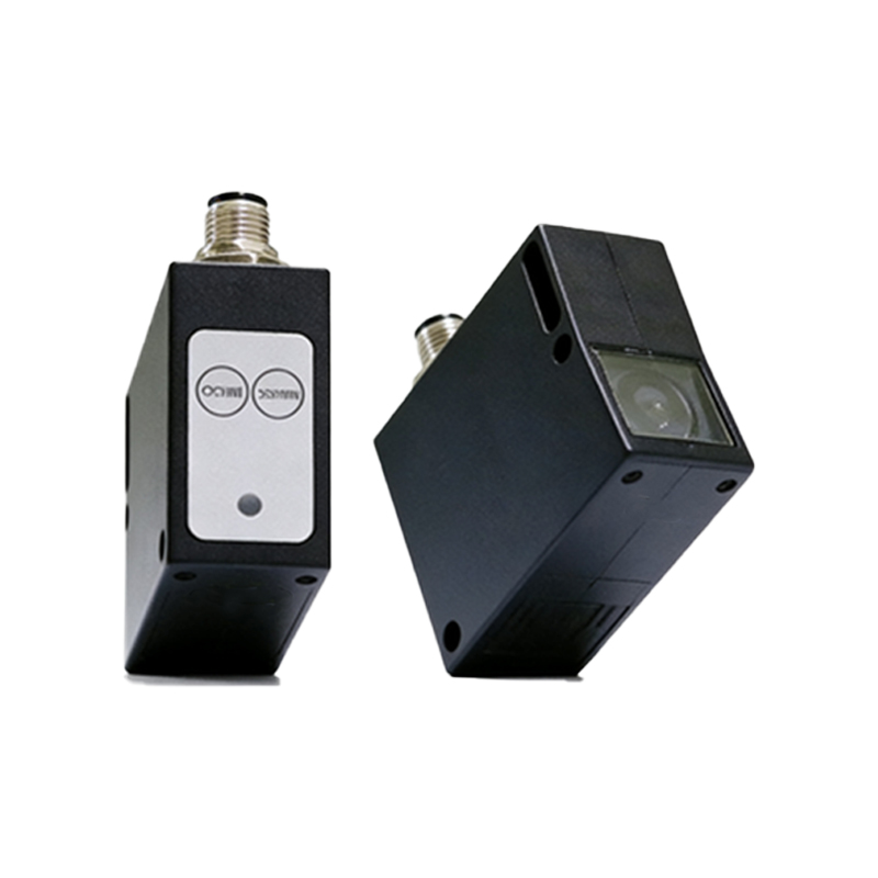
The internal structure of a standard photoelectric sensor can be deconstructed into several key subsystems. The heart of the emitter section is the Light Emitting Element, typically a Light Emitting Diode (LED) for visible or infrared light, or a laser diode for highly precise applications. This element is driven by an oscillator circuit that modulates the light at a specific frequency, which helps the sensor distinguish its own signal from ambient light interference. The emitted light is then collimated and focused through a Lens System to create a well-defined beam. The receiver section mirrors this setup in reverse. It contains a Photodetector, such as a phototransistor or photodiode, which converts the incoming light signal back into an electrical current. This weak signal is then amplified and processed by a dedicated receiver circuit. The entire assembly is housed in a rugged casing, often rated IP67 or higher, to withstand harsh industrial environments involving dust, moisture, and mechanical vibration.
Through-Beam Sensor Configuration
The through-beam, or opposed-mode, configuration represents one of the most robust and long-range sensing methods. In this structure, the emitter and receiver are housed in two separate units positioned directly opposite each other. The emitter projects a continuous or modulated beam of light towards the receiver unit. An object is detected when it physically interrupts this beam, causing a complete loss of signal at the receiver. The schematic diagram for this type clearly shows two distinct housings with alignment marks, connected to a power supply and control system. The key advantage of this structure is its high reliability and ability to work over very long distances, sometimes exceeding 100 meters. It is highly immune to environmental factors like target color, reflectivity, or surface angle, as it only detects the presence or absence of the beam.
Retroreflective Sensor Configuration
The retroreflective sensor offers a practical compromise between sensing range and installation convenience. Here, both the emitter and receiver are co-located within a single housing. The device emits a light beam towards a specially designed reflector, often a corner-cube retroreflector, which returns the light directly back to the receiver. Detection occurs when an object blocks this path between the sensor and the reflector. A structural diagram of this sensor highlights the single housing containing both optical elements and a polarization filter, which is a critical component. This filter ensures the sensor only recognizes light that has made the round trip to the reflector and back, ignoring simple reflections from shiny objects that might otherwise cause false triggers. This design is ideal for applications requiring moderate range with simpler wiring.
Diffuse Reflective Sensor Configuration
The diffuse reflective, or proximity-mode, sensor is the most compact and easiest to install, as it requires only a single unit and no separate reflector. The emitter and receiver are mounted in the same housing at an angle to each other. The emitter projects light onto the target surface, and the receiver detects the portion of this light that is diffusely reflected back. A detailed structural illustration shows the angled alignment of the lenses and the internal light path. Detection is highly dependent on the target's color, surface texture, and distance, as these factors greatly influence the amount of reflected light. Advanced versions incorporate background suppression technology or use time-of-flight principles to measure distance, making them less sensitive to color and more reliable for precise positioning tasks.
Signal Processing and Output Circuitry
Beyond the optical components, the electronic circuitry within the sensor is crucial for reliable operation. The received analog signal from the photodetector is extremely weak. It first passes through an amplifier stage to boost its strength. Subsequently, a demodulator circuit filters out the modulated frequency, effectively rejecting ambient light noise. The processed signal is then fed into a comparator circuit, which compares it to a preset threshold. When the signal crosses this threshold (indicating detection or loss of detection, depending on the logic), it triggers the output stage. This output typically consists of a solid-state switch (PNP/NPN transistor) or a relay, providing a clean digital signal (ON/OFF) to a Programmable Logic Controller (PLC) or other control systems. Modern sensors often include programmable functions, such as adjustable sensing range, timers, and teach-in capabilities, all managed by a built-in microcontroller.
Selection Criteria and Application Considerations
Choosing the correct sensor structure is paramount for system success. Engineers must evaluate several key parameters. Sensing Range is the maximum reliable detection distance, which varies dramatically between through-beam, retroreflective, and diffuse types. Beam Spot Size determines the minimum detectable object; a focused laser spot is needed for small parts. Response Time, often in microseconds, is critical for high-speed production lines. Environmental factors such as ambient light, dust, fog, and temperature extremes dictate the need for robust housing and modulated light sources. The target's properties—its size, color, material, and surface finish—directly influence the choice between different reflective modes. Finally, the required output type (digital NPN/PNP, analog 4-20mA, or IO-Link for digital communication) must integrate seamlessly with the existing control architecture. A thorough analysis of these factors against the application's demands ensures optimal sensor performance and longevity.