Understanding Photoelectric Sensor Wiring Basics
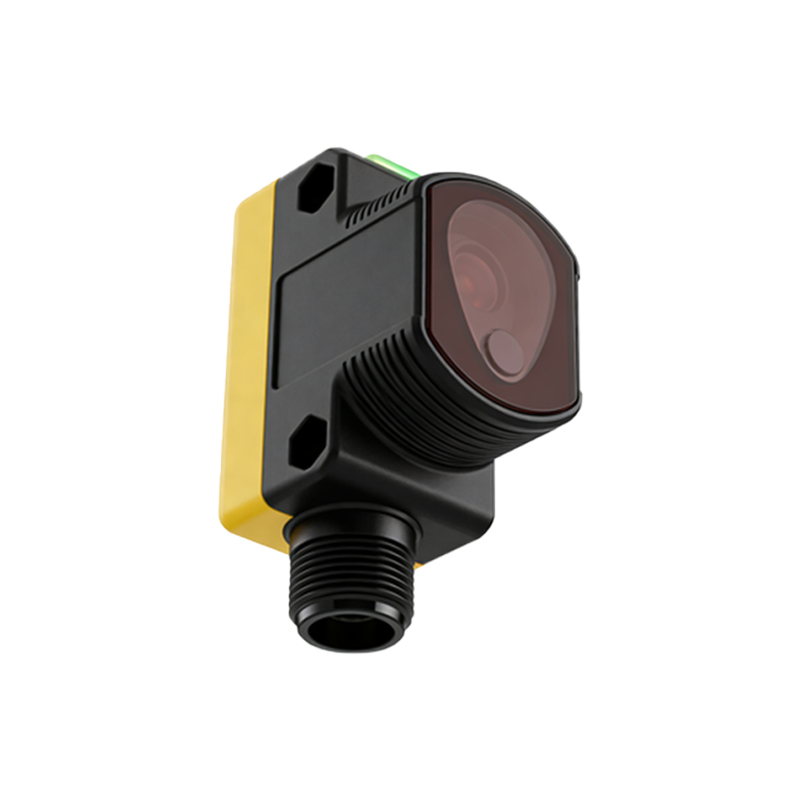
Photoelectric sensors are widely used in industrial automation for detecting the presence, absence, or distance of objects. Proper wiring is crucial for reliable operation, and crimping is a key technique for creating secure electrical connections. Crimping involves using a tool to compress a metal connector around a wire, ensuring a solid mechanical and electrical bond. This method is preferred over soldering in many industrial settings due to its durability, resistance to vibration, and ease of installation. Before starting, always refer to the sensor's datasheet for specific voltage, current, and wiring requirements. Typically, photoelectric sensors have three main wires: brown (positive), blue (negative), and black (output). Some models may include additional wires for functions like timing or analog output. Ensure you have the correct wire gauge and connector type as specified by the manufacturer.
Selecting the Right Tools and Materials
To achieve a professional crimp, you need appropriate tools and materials. Essential items include a high-quality crimping tool, wire strippers, and insulated terminals or connectors. The crimping tool should match the terminal type—for example, use a ratchet crimper for insulated terminals to ensure consistent pressure. Avoid using pliers or generic tools, as they can cause weak connections or damage. Choose terminals that fit the wire gauge; common sizes for sensor wiring are 22-18 AWG. Insulated terminals provide extra protection against short circuits. Additionally, have heat shrink tubing on hand if additional insulation is needed. Always use stranded wire for flexibility, and ensure it is rated for the sensor's voltage and temperature range. Labeling wires during installation can prevent errors in complex systems.
Step-by-Step Crimping Process
Begin by cutting the wire to the required length using wire cutters. Strip about 1/4 inch (6-7 mm) of insulation from the end, being careful not to nick the strands. Twist the strands lightly to keep them together. Insert the stripped wire into the terminal barrel until the insulation touches the barrel's edge. Place the terminal into the crimping tool's correct slot—usually color-coded or marked for wire gauge. Squeeze the tool firmly until it releases automatically, indicating a complete crimp. Check that the terminal is securely attached by gently pulling on it; if it slips off, re-crimp. For insulated terminals, the crimp should compress both the wire and insulation sleeve. Next, slide heat shrink tubing over the connection if needed, and apply heat to seal it. Repeat for all wires, ensuring consistent quality across connections.
Connecting Wires to the Photoelectric Sensor
Once all wires are crimped, connect them to the sensor's terminals. Most photoelectric sensors have screw terminals or plug-in connectors. For screw terminals, loosen the screw, insert the crimped terminal, and tighten securely—avoid over-tightening to prevent damage. If using plug-in connectors, align the terminal with the slot and push until it clicks into place. Double-check the wiring against the sensor diagram: typically, brown wire to positive (+), blue to negative (-), and black to output. For sensors with multiple outputs or functions, refer to the manual for correct assignments. After connections are made, organize wires with cable ties or conduits to reduce strain and interference. Ensure no exposed conductors are visible, and that the sensor housing is properly closed to protect against dust and moisture.
Testing and Troubleshooting Connections
After wiring, test the sensor to verify functionality. Power on the system and observe the sensor's indicator LED—it should light up if wired correctly. Use a multimeter to check voltage at the terminals: positive should match the supply voltage (e.g., 12-24 VDC), and output should change when an object is detected. If the sensor fails to operate, first inspect crimps for loose wires or poor contact. Re-crimp any questionable connections. Also, check for reversed polarity or short circuits. In noisy environments, consider using shielded cables and grounding the shield to reduce interference. Regular maintenance, such as inspecting connections for corrosion or wear, can prevent future issues. Document the wiring setup for easy reference during repairs or upgrades.
Best Practices for Long-Term Reliability
To ensure durable connections, follow industry best practices. Use only UL-listed or certified components for safety and compliance. Keep crimps clean and free of debris—contaminants can increase resistance and cause overheating. Apply strain relief by securing wires near the sensor to prevent tension on the terminals. In high-vibration areas, use locking terminals or adhesive-lined heat shrink for extra security. Avoid bending wires sharply, which can break strands over time. Train personnel on proper crimping techniques to maintain consistency. Periodically audit wiring installations as part of preventive maintenance. By prioritizing quality crimping, you enhance sensor performance, reduce downtime, and extend equipment lifespan in automation systems.