Understanding the Components and Their Roles
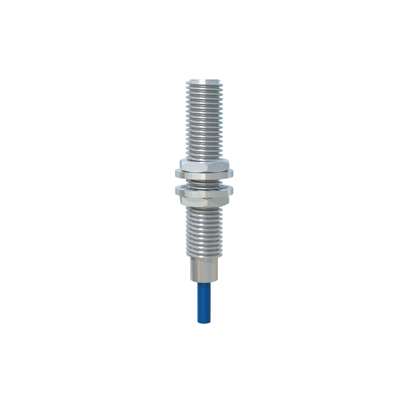
In industrial automation and machinery safety systems, the integration of a warning light with a proximity sensor is a fundamental yet critical task. A proximity sensor, often inductive or capacitive, detects the presence or absence of a metallic or non-metallic object without physical contact. Its output is typically a discrete signal—either a PNP (sourcing) or NPN (sinking) DC voltage. The warning light, or beacon, is a visual alert device that uses LEDs or halogen bulbs to signal a specific machine state, such as a fault, cycle completion, or safety breach. The core objective of connecting these two devices is to create a reliable, immediate visual response to a detected event, enhancing operational awareness and safety.
Reviewing Electrical Specifications and Wiring Diagrams
Before any physical connection, a thorough review of the datasheets for both the proximity sensor and the warning light is non-negotiable. Key parameters include the operating voltage (commonly 12-24V DC), current rating, output type of the sensor (PNP/NPN/NO/NC), and the input requirements of the warning light. Mismatched voltages or incorrect current handling can lead to device failure. The wiring diagram is your blueprint. For a standard 3-wire DC sensor, you will have a brown wire (+V), a blue wire (0V or common), and a black wire (signal output). The warning light will have terminals for power and, often, a separate input for the control signal.
Step-by-Step Connection Procedure for a PNP Sensor
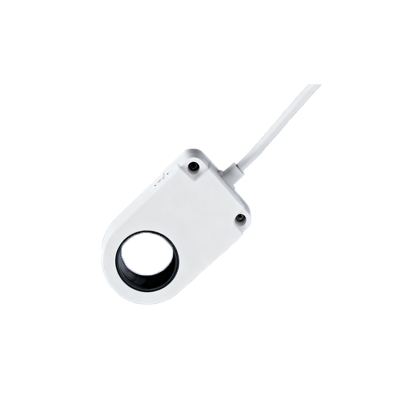
For a common setup using a 24V DC PNP (normally open) proximity sensor and a 24V DC warning light, follow this procedure. First, ensure the power supply is disconnected. Connect the brown wire from the sensor to the positive terminal (+24V) of your DC power supply. Connect the blue wire from the sensor to the negative terminal (0V) of the power supply. Now, take the black signal wire from the sensor. This wire will carry the +24V signal when an object is detected. Connect this black wire directly to the control input terminal of the warning light. Finally, connect the negative or common terminal of the warning light to the same 0V point as the sensor's blue wire. This creates a complete circuit where sensor activation provides power to the light.
Addressing NPN Sensor Configurations and Sinking Inputs
If using an NPN sensor, the logic is inverted. An NPN sensor sinks current to ground. In this configuration, the sensor's black wire connects to the warning light's control input, but the positive voltage for the light must be supplied separately. Connect the warning light's positive terminal to +24V. Connect its control input terminal to the sensor's black signal wire. The sensor's blue wire goes to 0V, and its brown wire to +24V. When the NPN sensor activates, it connects the light's control input to 0V, completing the circuit and illuminating the light. Always verify if your warning light has a "sinking" or "sourcing" input to match the sensor type.
Incorporating Intermediary Devices and Safety Considerations
In complex systems, a direct connection might not be feasible or safe. The sensor's signal often first goes to a Programmable Logic Controller (PLC) input module. The PLC program then processes the logic and activates an output module, which in turn powers the warning light. This allows for sophisticated logic, delays, and integration with other alarms. For safety-critical applications, always incorporate appropriate fuses or circuit breakers in the power lines to both devices. Use proper wire gauges, secure connections with ferrules, and employ cable ducts or conduits for protection. Functional testing with the machine in a safe mode is essential before full commissioning.
Troubleshooting Common Connection Issues
If the warning light fails to activate, begin troubleshooting systematically. First, use a multimeter to confirm power supply voltage at the sensor and light terminals. Check for loose connections or damaged wires. Verify the sensor is correctly detecting the target by measuring the voltage on its signal wire. For a PNP sensor, this should read near supply voltage when activated. Ensure the warning light's lamp or LED module is not burnt out. A common mistake is confusing PNP and NPN wiring, resulting in the light being constantly on or completely off. Always refer to the manufacturer's documentation for specific diagnostic LEDs or test procedures on the devices.