Introduction to Photoelectric Sensor Wiring
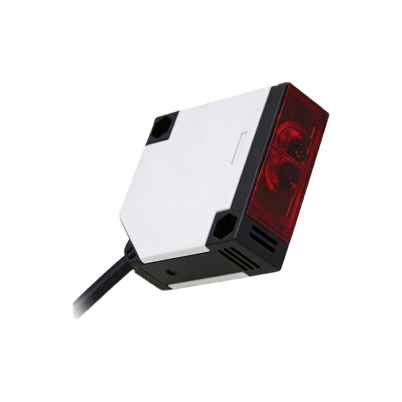
Photoelectric sensors are fundamental components in industrial automation, used for detecting the presence, absence, or distance of objects without physical contact. A common point of inquiry among technicians and engineers is the wiring configuration, particularly when encountering a sensor with four wires. Unlike simpler two-wire devices that handle both power and signal on the same pair, a four-wire photoelectric sensor offers distinct and separate connections for power supply and output switching. This design provides greater flexibility, reliability, and functionality in control systems. Understanding the purpose of each wire is crucial for correct installation, safe operation, and optimal performance within an electrical panel or machine.
Standard Color Coding for 4-Wire Sensors
While manufacturers may have variations, a nearly universal color code is adopted for DC-powered 4-wire photoelectric sensors. This standardization aids in global installation and maintenance. The typical wiring is as follows: Brown wire: This is the positive voltage supply line (+V). It must be connected to the positive terminal of your DC power source, commonly 10-30 VDC. Blue wire: This is the negative voltage supply line or common (0V). It must be connected to the negative terminal of your DC power source. Black wire: This is the output signal wire. It is typically the switched output from the sensor's internal transistor. White wire: This is often a second output signal wire or a complementary output. Its function depends on the sensor's output configuration (e.g., NPN/PNP, NO/NC). Always, without exception, consult the specific sensor's datasheet or manual for the definitive wiring diagram, as colors can differ, especially for AC sensors or special models.
Understanding Output Types: NPN vs. PNP
The function of the black and white wires is directly tied to the sensor's output transistor type, which is either NPN or PNP. This is a critical concept in sensor wiring. An NPN sensor, also known as a sinking sensor, switches the negative (0V) line to the load. In a typical NPN configuration, the black wire is the output. When active, it connects the load to the common (Blue, 0V). The load itself is connected to the positive supply (+V). Conversely, a PNP sensor, or sourcing sensor, switches the positive (+V) line to the load. Here, the black output wire, when active, supplies positive voltage to the load. The load is then connected to the common (0V). The white wire may provide the opposite logic output (e.g., if black is Normally Open, white may be Normally Closed) or a separate channel.
Step-by-Step Wiring Procedure
To correctly connect a 4-wire DC photoelectric sensor, follow this systematic procedure. First, identify your DC power source, ensuring its voltage matches the sensor's rated range (e.g., 24 VDC). Second, permanently disconnect power to the circuit before beginning any wiring work. Third, connect the Brown wire to the positive (+) terminal of your power supply. Fourth, connect the Blue wire to the negative (-) terminal of your power supply. This completes the power circuit. Fifth, identify your load device, such as a PLC input, relay coil, or indicator lamp. Sixth, determine the sensor's output type (NPN or PNP) and the desired switching logic (NO or NC) for the black wire. For an NPN sensor, connect one side of the load to +V, and the other side to the sensor's Black wire. For a PNP sensor, connect one side of the load to 0V (Blue), and the other side to the sensor's Black wire. The white wire is connected based on your control logic needs.
Connecting to a Programmable Logic Controller (PLC)
Integrating a 4-wire sensor with a PLC is a standard application. The process clarifies the NPN/PNP distinction. For a sinking-input PLC module (common in some regions), you would use a PNP (sourcing) sensor. Connect the sensor's Brown to +24VDC, Blue to 0VDC. Connect the sensor's Black output wire directly to the PLC's input terminal. The PLC input card's common is internally connected to 0VDC, completing the circuit when the sensor activates. For a sourcing-input PLC module, you would use an NPN (sinking) sensor. The wiring is similar, but the PLC input common is internally connected to +24VDC. Mismatching sensor and PLC input types will result in a non-functional circuit. The white wire can be wired to a separate PLC input for complementary signaling or alarm monitoring.
Common Troubleshooting and Safety Tips
If a newly wired sensor fails to operate, methodically check these points. Verify power supply voltage at the Brown and Blue wires with a multimeter. Confirm the polarity is correct; reversed polarity can damage the sensor. Check if the output indicator LED on the sensor is illuminating when an object is detected. If it lights but the load doesn't activate, the issue is in the output circuit. Use your multimeter to check for voltage (for PNP) or continuity to 0V (for NPN) at the Black wire when the sensor is active. Ensure the load device is functional and its current draw is within the sensor's rated switching capacity. Always adhere to local and national electrical codes. Use proper gauge wire, secure connections with ferrules or terminal blocks, and implement appropriate overcurrent protection like fuses. Never modify sensor wiring under power.
Conclusion and Best Practices
A four-wire photoelectric sensor provides a robust and clear interface for industrial controls by separating power and signal paths. The key to successful connection lies in three steps: identifying the standard color codes, determining the output transistor type (NPN or PNP), and understanding the requirements of the load device. Always prioritize the manufacturer's documentation over general guidelines. Proper wiring ensures not only functionality but also protects against electrical noise, voltage spikes, and potential damage to sensitive control equipment like PLCs. By mastering these connections, engineers and technicians can reliably deploy these versatile sensors for counting, positioning, inspection, and countless other automation tasks, forming the sensory backbone of modern manufacturing systems.