Understanding Photoelectric Sensor Basics
Photoelectric sensors, such as those manufactured by Denso Opto, are pivotal components in industrial automation for detecting the presence, absence, or distance of objects without physical contact. These sensors operate by emitting a light beam—typically infrared, visible red, or laser—and detecting changes in the received light intensity. The core principle involves a transmitter and a receiver. In through-beam types, these are separate units, while in retro-reflective or diffuse-reflective models, they are housed together. The sensor triggers an output signal when the light path is interrupted or altered by an object. A solid grasp of these operational modes is the foundation for precise adjustment and reliable application in diverse environments, from assembly lines to packaging machinery.
Pre-Adjustment Preparation and Safety
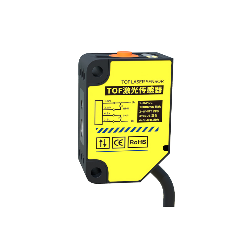
Before initiating any adjustment procedures, thorough preparation is essential to ensure safety and accuracy. First, consult the specific technical manual for your Denso Opto sensor model, as specifications and adjustment methods can vary. Power down and lock out the electrical circuit to prevent accidental activation. Ensure the sensor and target object are clean and free from obstructions. Verify the installation is secure and properly aligned. Gather necessary tools, which may include a small screwdriver for potentiometer adjustments and a measuring device if precise distances are required. Establishing a stable environment, minimizing ambient light interference, and having the sensor's indicator lights visible are critical preparatory steps for a successful calibration process.
Adjusting Sensitivity and Threshold Levels
The most common adjustment for Denso Opto photoelectric sensors involves fine-tuning the sensitivity or threshold level. This is typically done via a potentiometer on the sensor body, often labeled "SENS" or marked with a plus/minus symbol. The goal is to set a detection threshold that reliably identifies the target while ignoring background noise or minor environmental fluctuations. To adjust, introduce the standard target object at the required sensing distance. Slowly rotate the potentiometer until the sensor's output indicator (usually an LED) changes state, signifying detection. Then, slightly adjust the potentiometer beyond this point to establish a safety margin, ensuring consistent operation even with slight variations in target color, reflectivity, or environmental conditions like dust or vibration.
Setting the Response Time and Hysteresis
Advanced Denso Opto sensors offer adjustments for response time and hysteresis. Response time controls how quickly the sensor reacts to a change in detection status. A faster time is needed for high-speed applications but can make the sensor prone to noise; a slower time filters out noise but may miss rapid events. Adjust this setting based on the speed of your application. Hysteresis is the difference between the turn-on and turn-off points. It prevents output chattering when the target is near the detection boundary. Increasing hysteresis provides a more stable output at the cost of slightly reduced positional accuracy. Adjust these parameters incrementally while testing with the actual target under real operating conditions to find the optimal balance for system stability.
Beam Alignment for Through-Beam and Retro-Reflective Sensors
Precise beam alignment is crucial for through-beam and retro-reflective sensor models. For through-beam types, carefully align the separate transmitter and receiver units so that the beam is centered on the receiver's lens. Use the sensor's alignment indicators, which often show signal strength. Adjust until the indicator shows maximum strength. For retro-reflective sensors using a reflector, align the sensor perpendicularly to the reflector center. Even minor misalignment can drastically reduce sensing distance or cause failure. After rough alignment, use the sensitivity adjustment to fine-tune the system. In challenging environments, consider using a laser model for a visible beam, which significantly simplifies the alignment process.
Dealing with Environmental Interference
Industrial environments present challenges like ambient light, dust, moisture, and electrical noise. Denso Opto sensors incorporate features to mitigate these, but proper adjustment is key. For ambient light from sunlight or factory lighting, use a modulated light sensor and ensure its operating frequency is set correctly. Some models allow frequency selection to avoid crosstalk with nearby sensors. For dusty or foggy conditions, increase the sensitivity margin to compensate for light attenuation. Ensure the lens is kept clean. For electrical noise from motors or drives, ensure proper grounding and shielding of cables. If interference persists, slightly lengthen the response time to filter out electrical noise pulses. Always validate sensor performance under the actual worst-case operating conditions.
Verification and Maintenance Practices
After completing adjustments, a rigorous verification process is mandatory. Test the sensor with the target object across the entire required sensing range and at different speeds. Check for false triggers by introducing non-target objects into the vicinity. Monitor the sensor's performance over an extended period, such as a full production cycle. Document the final potentiometer positions and settings for future reference. Establish a routine maintenance schedule. Regularly inspect the sensor lens for cleanliness, check mounting stability, and verify electrical connections. Periodically re-verify the adjustment, especially if the process or environment changes. Proactive maintenance based on the sensor's operational data ensures long-term reliability and prevents unplanned downtime.