Introduction to Photoelectric Sensor Components
Photoelectric sensors are essential devices in industrial automation, relying on internal circuits to detect objects through light beams. The core components include a light emitter, a receiver, and signal processing circuitry. The emitter typically uses an LED or laser diode to generate infrared or visible light, while the receiver consists of a phototransistor or photodiode to capture reflected or transmitted light. These elements are integrated into a compact housing, ensuring durability in harsh environments like manufacturing lines. The internal circuit diagram illustrates how these parts interact, converting light signals into electrical outputs for control systems. Understanding this setup is crucial for engineers designing reliable sensing solutions.
Emitter Circuit Design and Operation
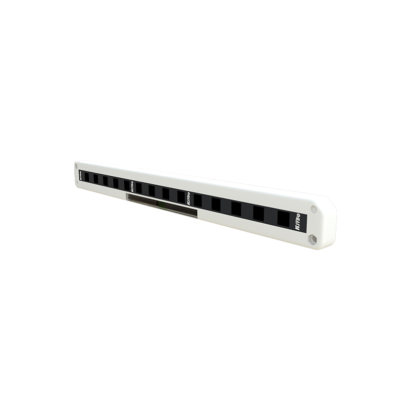
The emitter circuit in a photoelectric sensor drives the light source, often employing a constant current supply to maintain stable light output. A typical diagram shows a transistor or integrated driver IC connected to the LED, with resistors to limit current and prevent overheating. For pulsed operation, a modulation circuit adds a high-frequency signal, reducing interference from ambient light. This section of the circuit ensures efficient light transmission, with components like capacitors filtering noise. Engineers optimize this design for energy efficiency and long lifespan, critical in continuous industrial applications.
Receiver Circuit and Signal Amplification
On the receiver side, the photodiode or phototransistor converts incoming light into a weak electrical current. The circuit diagram includes an amplifier stage, often using operational amplifiers (op-amps) to boost this signal. Feedback resistors set the gain, while filters remove unwanted frequencies from background light. A comparator circuit then thresholds the amplified signal, distinguishing between presence and absence of an object. This precise amplification is vital for accurate detection, especially in low-light conditions or with reflective surfaces.
Signal Processing and Output Stages
After amplification, the signal undergoes processing to enhance reliability. The internal diagram features microcontrollers or dedicated ICs that analyze pulse patterns, enabling modulation decoding for noise immunity. Output stages include transistors or relays to interface with external devices like PLCs, providing digital (ON/OFF) or analog signals. Protection components, such as diodes and fuses, safeguard against voltage spikes. This section ensures the sensor delivers consistent performance, even in electrically noisy environments.
Power Supply and Regulation Circuitry
Photoelectric sensors require stable power, often from 12-24V DC sources. The circuit diagram incorporates voltage regulators and capacitors to smooth input power, preventing fluctuations from affecting sensitivity. Some designs include reverse polarity protection and surge suppression. Efficient power management extends sensor life and reduces downtime, making this a key focus in industrial-grade models. Engineers balance compactness with robustness in this subsystem.
Applications and Circuit Adaptations
Different applications, such as object counting or color detection, lead to circuit variations. For example, background suppression sensors add specialized circuits to ignore distant reflections. Diagrams show adjustable potentiometers for sensitivity tuning, allowing customization in the field. By studying these adaptations, professionals can select or modify sensors for specific tasks, enhancing system integration and performance.
Conclusion and Maintenance Insights
Mastering the internal circuit diagram empowers engineers to troubleshoot and optimize photoelectric sensors. Regular checks of components like emitters and connectors prevent failures. As technology advances, circuits evolve with smarter features, but core principles remain. This knowledge supports innovation in automation, driving efficiency across industries.