Understanding the Core Operating Principle
A retro-reflective photoelectric sensor operates by emitting a beam of light, typically from an LED, towards a specialized reflector. This reflector, often a corner-cube prism, is designed to return the light beam directly to the sensor's receiver, regardless of the angle of incidence. The internal logic of the sensor is set to detect the presence of an object when this returned beam is interrupted or significantly diminished. This fundamental principle makes it a versatile solution for detecting a wide range of materials, from opaque objects to translucent films, depending on the sensor's sensitivity settings and the strength of the returned signal. The key advantage over through-beam sensors is the simplified installation, requiring wiring only on one side of the application, while offering a longer sensing range than diffuse models.
Pre-Installation Considerations and Mounting
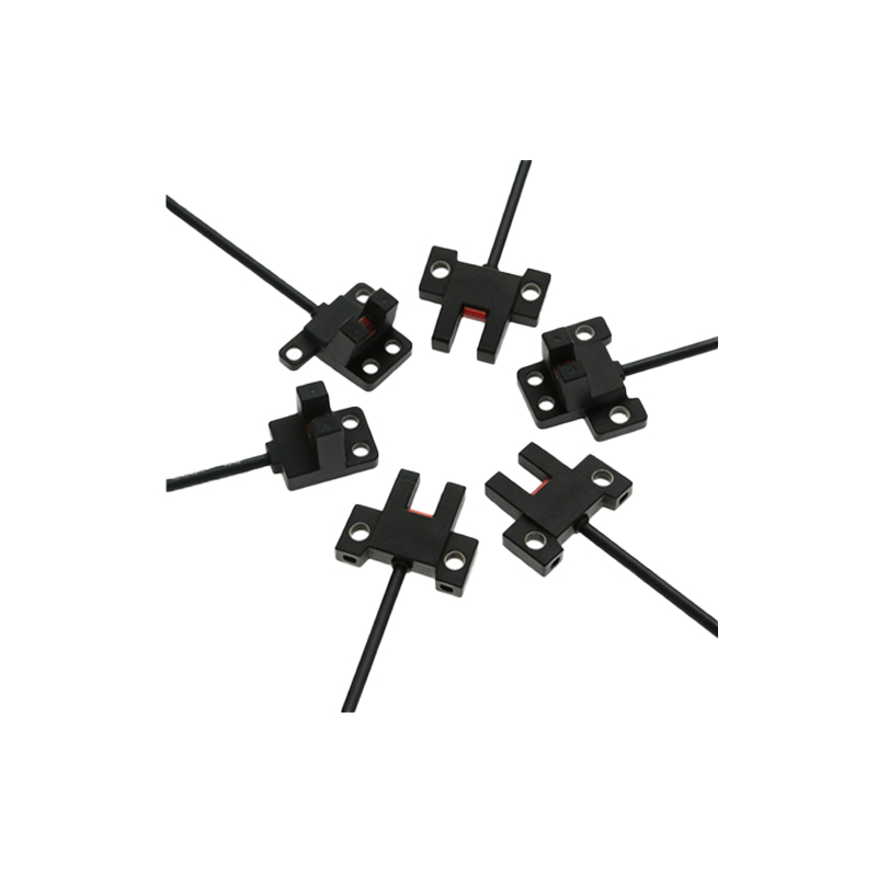
Successful calibration begins with proper physical setup. Ensure the sensor and reflector are mounted on stable, vibration-free surfaces. Alignment is paramount; the sensor's beam must strike the center of the reflector squarely. Even minor angular misalignment can drastically reduce the effective sensing range and signal strength. Maintain a clean environment, as dust, dirt, or moisture on the lens or reflector surface are common sources of failure. Consider the target object's characteristics—its size, color, and surface texture—as these will influence the necessary beam intensity and receiver sensitivity. For small or highly reflective targets, precise alignment is even more critical to avoid false triggers from stray reflections.
Initial Power-Up and Alignment Verification
After securing power connections according to the manufacturer's specifications, power on the sensor. Most modern retro-reflective sensors feature a visible red or green LED beam for alignment assistance. Activate this function if available. Carefully adjust the sensor's position until the beam is centered on the reflector. Observe the sensor's status indicator (usually a separate LED). A stable "lit" or "green" indicator typically confirms proper alignment and reception of the reflected beam. Some advanced models offer a digital display or remote teach-in capability via IO-Link, providing a numerical value for the received signal strength, which is invaluable for precise setup.
Calibrating Sensitivity and Setting the Threshold
This is the most critical step for reliable operation. The goal is to set a detection threshold that reliably distinguishes between the "beam present" state (clear path to reflector) and the "beam blocked" state (object present). Using a setup tool, button sequence, or remote command, place the sensor in "teach" or "calibration" mode. First, present the sensor with a "clear" condition (no target object). The sensor will learn and store this as the baseline signal strength. Next, introduce a representative target object into the beam path and trigger the second step of the teach sequence. The sensor calculates an optimal threshold between these two values. For challenging applications with low contrast (e.g., detecting a clear bottle), fine-tune the sensitivity manually to maximize the margin between the two states, preventing false positives.
Advanced Functionality: Background Suppression and Timing
Many retro-reflective sensors incorporate Background Suppression (BGS) technology. This feature allows the sensor to ignore objects beyond a preset distance, effectively defining a precise sensing window. Calibrating BGS involves teaching the sensor the exact distance to the reflector or the desired limit of the sensing field. Furthermore, configure output timing functions such as ON-Delay, OFF-Delay, or One-Shot to condition the sensor's response. These filters help debounce signals in unstable environments, ensuring a clean, sustained output signal only when a valid detection event occurs, which is crucial for interfacing with PLCs and control systems.
Systematic Troubleshooting Common Issues
Persistent problems require a methodical approach. First, verify power supply voltage and polarity. If the sensor has no power indicator, check with a multimeter. For false triggers or failure to detect, re-check alignment and clean all optical surfaces. Use the sensor's signal strength indicator to diagnose a weak return beam. If the signal is low, suspect misalignment, dirty optics, a damaged reflector, or an insufficiently powerful sensor for the required range. Interference from ambient light can be mitigated by selecting a sensor with a modulated LED beam and checking for direct sunlight or other strong light sources hitting the receiver. Finally, verify the load connected to the sensor's output is within its specified ratings.
Implementing Best Practices for Long-Term Reliability
To ensure sustained performance, establish a routine maintenance schedule. Periodically inspect and clean the sensor lens and reflector. In harsh environments, consider protective housings or air purges to keep optics clear. Document the calibrated sensitivity settings and signal strength values for future reference and quicker recovery after maintenance shutdowns. For critical applications, implement a redundancy system using two sensors in a voting logic arrangement. Always refer to the manufacturer's datasheet for specific details regarding sensing range derating, environmental limits, and recommended mounting hardware, as these factors are essential for achieving the published performance and long operational life.