Understanding Proximity Switch Sensors in Robotic Applications
Proximity switch sensors are fundamental components in modern robotic arm systems, providing non-contact detection of metallic or non-metallic objects. These sensors play a critical role in ensuring precise positioning, end-of-arm tooling control, and safety interlocks. In industrial automation, inductive proximity sensors are predominantly used for detecting metallic parts, while capacitive types can sense a wider range of materials. The correct wiring and integration of these sensors are paramount for reliable operation. A malfunctioning sensor due to improper wiring can lead to production downtime, inaccurate pick-and-place operations, or even safety hazards. Therefore, a thorough understanding of the wiring diagram is not just a technical requirement but a necessity for system integrity and operational efficiency.
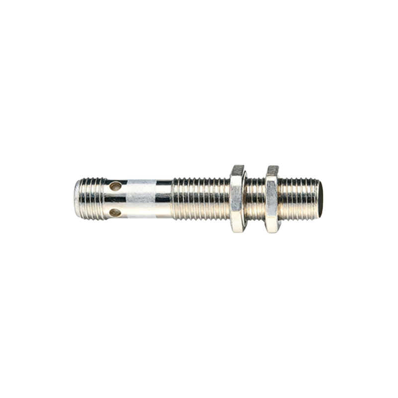
Key Components and Sensor Specifications
Before examining the wiring diagram, it is essential to identify the key components. A standard three-wire DC proximity sensor typically includes a brown wire (for positive supply, +V), a blue wire (for negative supply, 0V or common), and a black wire (for the switched output signal). Some sensors may have a white wire for a complementary output or other functions. The sensor's specification sheet, or datasheet, is the primary reference. It details the operating voltage range (commonly 10-30V DC), output type (NPN sinking or PNP sourcing), current rating, and switching frequency. For robotic arms, sensors with high switching frequencies and robust housing (IP67 or higher) are often selected to withstand the dynamic environment and potential exposure to coolants or debris.
Standard Three-Wire DC Sensor Wiring Configuration
The wiring diagram for a three-wire DC sensor to a Programmable Logic Controller (PLC) or robot controller is straightforward but must be followed meticulously. For a PNP (sourcing) type sensor: connect the brown wire to the positive DC supply terminal (e.g., +24V). Connect the blue wire to the negative DC supply terminal (0V or DC common). The black output wire is then connected to the designated digital input channel on the controller. The controller's input module must be compatible with a sourcing signal; it typically has an internal connection to the common (0V). For an NPN (sinking) type sensor, the wiring is similar, but the output logic is inverted. The brown wire still connects to +V, and the blue to 0V. However, the black output wire connects to the controller input, and the controller input's common terminal must be connected to the positive supply (+V). Misconfiguration between PNP and NPN types is a common wiring error that prevents signal detection.
Integration with Robotic Arm Controller I/O Modules
Integrating the sensor into the robotic arm's control system requires careful planning. The digital input module of the robot controller must match the sensor's output characteristics. The wiring diagram should account for the controller's internal circuitry. Often, a separate diagram for the I/O rack layout is used. It is standard practice to include a fuse (1-2 Amps) or a circuit breaker in the positive supply line to protect the wiring and the controller input. Additionally, for noise immunity in electrically noisy industrial environments, shielded cables are recommended. The shield should be grounded at only one end, typically at the controller's ground terminal, to prevent ground loops. The sensor's load (the controller input) must not exceed its maximum current rating to ensure longevity and reliable switching.
Wiring for Complementary and Analog Sensors
Some advanced robotic applications utilize sensors with complementary outputs (NO and NC) or analog output signals. For a four-wire sensor with complementary outputs, the wiring diagram includes the standard brown (+V), blue (0V), black (Normally Open output), and white (Normally Closed output) wires. Both output wires can be connected to separate controller inputs for redundant monitoring or complex logic sequences. Analog output sensors, which provide a voltage or current signal proportional to the detection distance, require connection to an analog input module. The wiring follows the same power supply principles, but the output wire (often black or gray) connects to the analog input channel. The reference voltage and signal range (e.g., 0-10V or 4-20mA) must be configured in the controller's software to interpret the distance data correctly for precision positioning.
Practical Installation and Troubleshooting Tips
During installation, always de-energize the control circuit. Secure all wire connections using appropriate terminals, such as ferrule crimps, to prevent loose strands and potential short circuits. Maintain proper cable management, avoiding sharp bends and keeping sensor cables away from high-power motor leads to minimize electromagnetic interference.