Understanding Metal Proximity Sensor Fundamentals
Metal proximity sensors, often referred to as inductive proximity sensors, are non-contact devices designed to detect the presence of metallic objects. They operate on the principle of electromagnetic induction, where an oscillator generates a high-frequency electromagnetic field from the sensor's active face. When a metal target enters this field, eddy currents are induced in the target, causing a change in the oscillation amplitude. This change is detected by the sensor's circuitry, which then triggers a solid-state output switch. Understanding this fundamental operation is crucial before installation, as it directly influences placement, sensing distance, and environmental considerations. Key specifications to review include the nominal sensing distance (Sn), the type of output (e.g., NPN, PNP, NO, NC), the housing material (typically nickel-plated brass or stainless steel), and the required supply voltage (commonly 10-30V DC).
Pre-Installation Planning and Site Assessment
A thorough site assessment is the most critical step for ensuring long-term sensor reliability. Begin by identifying the target metal's characteristics, such as its type (steel, aluminum, copper), size, shape, and approach speed. Standard sensing distances are calibrated for mild steel; for other metals, a correction factor must be applied (e.g., sensing distance for aluminum is typically 40-50% of the rated Sn). Evaluate the operating environment for potential hazards like excessive vibration, mechanical shock, temperature extremes, or the presence of cutting fluids, coolants, or metal chips. Ensure the selected sensor's IP (Ingress Protection) or NEMA rating is suitable for the environment—IP67 is common for washdown or dusty areas. Finally, verify that the electrical characteristics of the sensor (output current, leakage current, etc.) are compatible with the PLC or controller input module it will connect to.
Mechanical Mounting Procedures and Best Practices
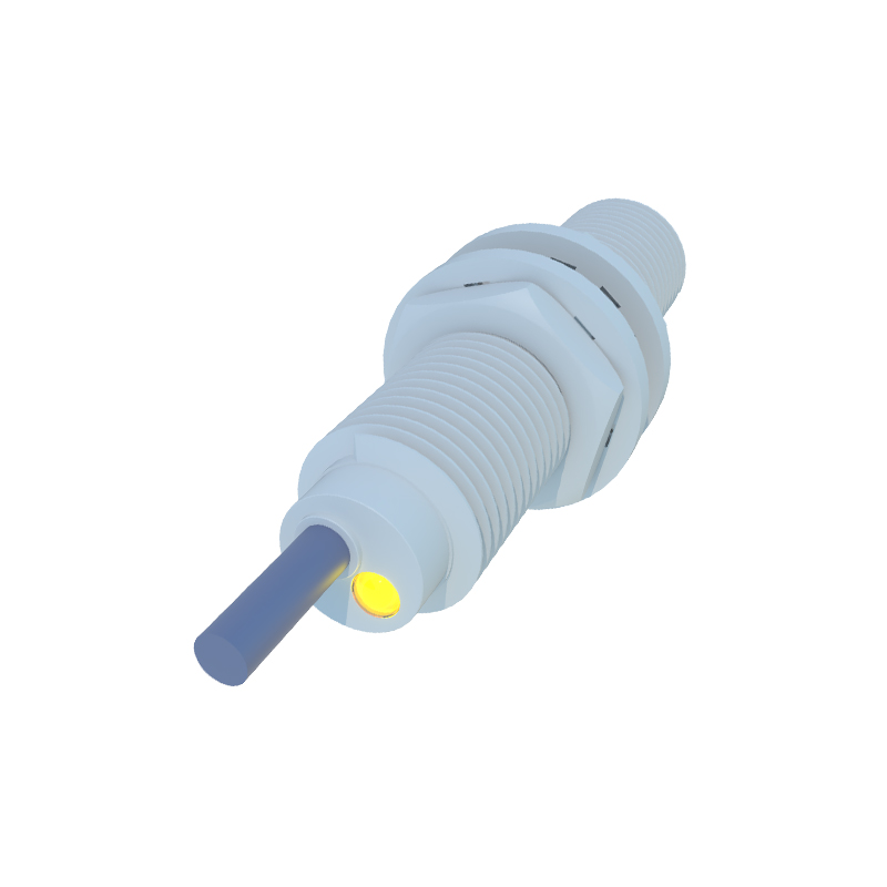
Correct mechanical mounting ensures accurate and repeatable detection. First, ensure the mounting surface is clean, flat, and rigid to prevent misalignment or vibration. For flush-mountable sensors, they can be installed flush with a metal bracket without affecting the sensing range. For non-flush (shielded) sensors, maintain the recommended clearance from surrounding metals as specified in the datasheet; typically, a lateral clearance of one sensor diameter and a frontal clearance of three times the Sn is advised to prevent false triggering. Use appropriate locknuts or mounting brackets to secure the sensor firmly. When sensing a specific area of a target, such as a gear tooth or a small tab, align the sensor's active face precisely perpendicular to the target's approach path. For applications involving fast-moving targets, consider a slight lead distance to account for the sensor's response time.
Electrical Wiring and Connection Guidelines
Proper electrical installation prevents damage to the sensor and connected equipment. Always disconnect power before making connections. Carefully follow the wiring diagram provided with the sensor, which is usually printed on the housing or in the manual. For DC 3-wire sensors, the standard color coding is brown for positive (+V), blue for common (0V), and black for the output signal. Ensure correct polarity. Use shielded cable in electrically noisy environments, connecting the shield to ground at the controller end only to prevent ground loops. Keep sensor cables separate from high-voltage AC power lines and motor leads to avoid inductive interference. If using a cable gland for ingress protection, ensure it is properly tightened to maintain the sensor's IP rating. For sensors with short-circuit, overload, and reverse polarity protection, these features add robustness but do not substitute for correct wiring.
Commissioning, Testing, and Alignment Verification
After mechanical and electrical installation, commissioning is essential. Re-apply power and observe the sensor's indicator LED (if equipped). Most sensors have a stable LED for power-on and a blinking or color-changing LED for target detection. Introduce the target metal to the sensing face at the required operational distance. Verify that the output switches reliably and that the sensing repeatability is within acceptable limits. Use a multimeter to check the output voltage state. For critical applications, perform a "null" test by running the machine or process without a target to ensure no false signals are generated due to vibration or stray metals. Fine-tune the sensor's position if necessary. Document the final mounting position and sensing gap for future maintenance reference.
Troubleshooting Common Installation Issues
Several common issues can arise post-installation. If the sensor fails to detect, verify power supply voltage, wiring connections, and that the target is within the effective sensing range and is of sufficient size. Inconsistent detection may be caused by target misalignment, vibration, or an unstable power supply. False triggering is often due to