Understanding Proximity Sensor Fundamentals
Proximity sensors are non-contact electronic devices designed to detect the presence or absence of an object within a defined sensing range without physical contact. They operate on various principles, including inductive, capacitive, ultrasonic, and photoelectric technologies. The core function is to provide a reliable electrical signal when a target enters the sensor's field. Selecting the correct type is the first step, but the installation location is equally critical for ensuring consistent, accurate, and long-term operation. An improperly placed sensor can lead to false triggers, missed detections, mechanical damage, and costly downtime. The optimal position is determined by a confluence of factors: the sensor's technology, the target material's properties, the required sensing distance, and the specific environmental conditions of the application.
Key Factors Determining Installation Location
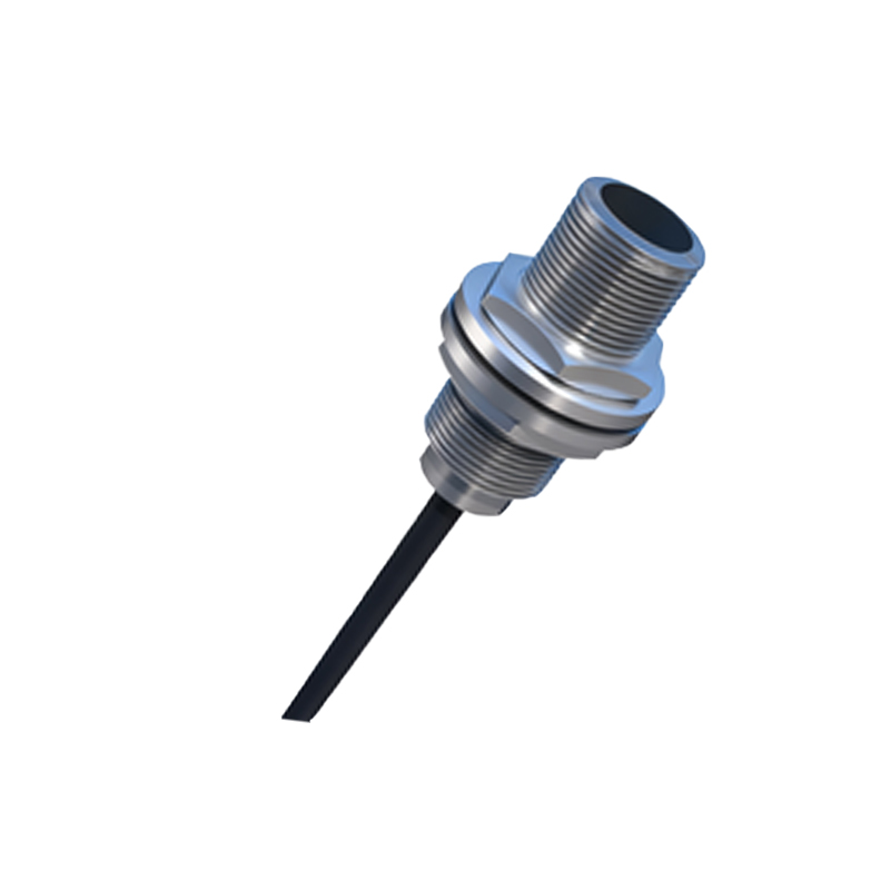
Several technical parameters dictate the ideal mounting spot. First is the rated sensing distance (Sn). This is the nominal operating distance under standardized conditions. For reliable operation, the actual installation distance should be 70-80% of the rated Sn to account for supply voltage fluctuations, temperature variations, and target material tolerances. Second is the target material and size. Inductive sensors, for instance, require ferrous or non-ferrous metal targets of a sufficient minimum size. The target must fully enter the sensor's active face area for a stable signal. Third is the environmental context. Factors like ambient temperature, presence of cutting fluids, metal chips, dust, vibration, and electromagnetic interference can severely impact performance. The location must mitigate these influences, sometimes requiring protective housings or strategic placement away from interference sources.
Optimal Positioning for Common Industrial Applications
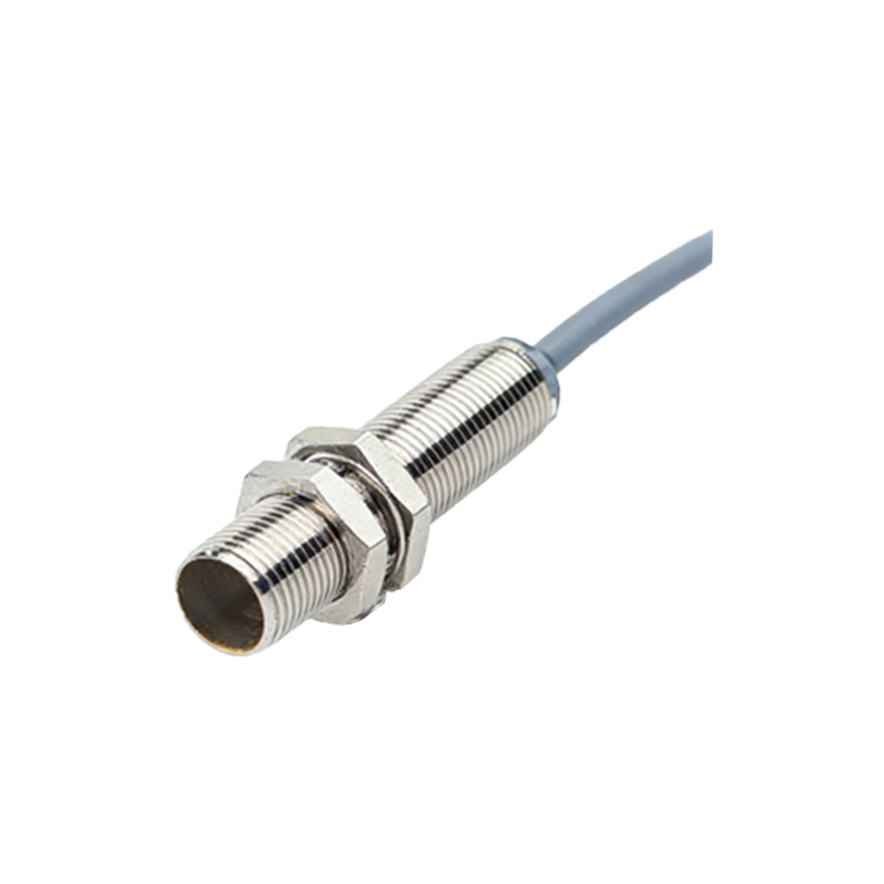
In machine automation, a primary application is position verification. For end-of-travel detection on linear actuators or cylinders, the sensor should be mounted parallel to the direction of movement, aligning with the actuator's built-in trigger magnet or flag. The sensing face should be positioned so the target passes directly across it at the precise point confirmation is needed. For rotary applications, such as detecting the presence of a gear tooth or a key on a shaft, mounting is typically radial. The sensor is fixed close to the rotating element, ensuring the target passes within its sensing range once per revolution. Critical clearance must be maintained to prevent physical contact due to shaft run-out or thermal expansion.
Installation Geometry and Alignment Best Practices
Precise mechanical alignment is non-negotiable. The sensor's sensing face must be perpendicular to the approach direction of the target for maximum sensitivity. Angular misalignment reduces the effective sensing distance. For cylindrical barrel-style sensors, flush mounting (where the sensing face is level with the surrounding metal surface) is possible only with models designed for it, as they have reduced lateral sensing fields to avoid detecting the mounting bracket. Non-flush mount sensors must protrude and require a clearance zone around the active face, free of any metallic or other interfering materials, as specified in the datasheet. Always secure the sensor firmly using the recommended torque on the lock nut to prevent loosening from vibration.
Mitigating Environmental and Interference Challenges
The installation site must be evaluated for potential electrical and physical interference. When mounting multiple inductive sensors side-by-side, maintain a minimum separation distance to prevent mutual interference, which can cause erratic switching. This distance is typically 2-3 times the sensor diameter for flush-mounted types and more for non-flush types. In wet or dirty environments, position sensors to avoid direct spray or accumulation of debris on the sensing face. In high-vibration areas, use sensors with robust housings and consider additional mechanical damping. For applications involving welding equipment, use weld-field immune sensors and locate them as far as practically possible from strong magnetic fields to prevent malfunction.
Special Considerations for Different Sensor Types
While inductive sensors are common for metals, other types have unique siting requirements. Capacitive sensors, used for non-metals, are highly sensitive to changes in the dielectric constant of their surroundings. Their installation must be fixed relative to any background material (like a container wall) to prevent false triggering from humidity or material buildup. Ultrasonic sensors require a clear "acoustic path" to the target. The location must be free of obstructions and soft, sound-absorbing materials that could scatter the sound wave. Photoelectric sensors demand a clear line of sight between the emitter and receiver (or reflector). The mounting point must be stable, as even slight misalignment from vibration can break the beam, and the lens must be kept clean.
Practical Steps for Installation and Verification
A systematic approach ensures success. First, thoroughly review the sensor datasheet for specifications on sensing distance, target size, temperature range, and mounting instructions. Second