Understanding Cylindrical Photoelectric Sensor Basics
Before beginning the installation process, it is crucial to understand the fundamental components and operating principles of a cylindrical photoelectric sensor. These sensors typically consist of a cylindrical housing containing an emitter (light source) and a receiver. They operate by detecting the presence, absence, or distance of an object based on the interruption or reflection of a light beam. Common types include through-beam, retro-reflective, and diffuse reflective models. Each type has specific installation considerations related to alignment, sensing distance, and environmental factors. Familiarize yourself with the sensor's datasheet, paying close attention to its nominal sensing range, light source type (often infrared or visible red), output configuration (PNP/NPN), and required supply voltage. This preliminary knowledge is essential for selecting the correct mounting location and ensuring reliable operation.
Selecting the Optimal Mounting Location
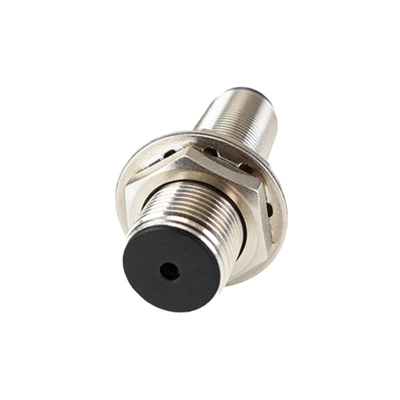
Choosing the correct installation point is paramount for sensor performance and longevity. First, identify the target object's path and the precise point where detection is required. Ensure the mounting location provides a stable, vibration-free surface. Consider the sensor's specified environmental ratings for factors like temperature, humidity, and potential exposure to dust, water, or chemicals (look for IP ratings). The location must allow for proper alignment between the emitter and receiver for through-beam types, or between the sensor and reflector for retro-reflective models. For diffuse sensors, ensure the background behind the target object is non-reflective and distant enough to avoid false triggers. Always maintain the recommended minimum and maximum sensing distances as per the manufacturer's specifications to guarantee consistent detection.
Preparing for Installation and Mounting
Begin by disconnecting all power sources to the machinery or control system to ensure safety. Most cylindrical photoelectric sensors are designed for easy mounting using standard brackets or nuts that fit into the sensor's threaded barrel. Common thread sizes include M8, M12, M18, and M30. Secure the sensor firmly using the provided lock nut or a suitable mounting bracket. Avoid overtightening, as this can damage the housing or threads. For through-beam sensors, mount the emitter and receiver units on opposite sides of the detection path. Ensure they are positioned at the same height and are perfectly coaxial. For retro-reflective sensors, mount the single sensor unit and position the reflector plate directly opposite. Use alignment tools or the sensor's built-in alignment indicator (often an LED) to achieve preliminary positioning.
Wiring and Electrical Connections
Correct wiring is critical for both functionality and safety. Refer to the sensor's connection diagram, typically found on its label or datasheet. Standard wire color coding is common: brown for positive supply voltage (+V), blue for common negative (0V), and black (for PNP) or white (for NPN) for the switched output signal. Some sensors also have a wire for output status indication. Use shielded cables in electrically noisy environments and ground the shield properly at the controller end. Ensure wires are securely connected to the correct terminals, often via a removable connector or a cable gland. After wiring, double-check all connections for accuracy before applying power. Proper strain relief for the cable is essential to prevent wire breakage from vibration or movement.
Precise Alignment and Fine-Tuning
Once mounted and wired, apply power to initiate the alignment process. Most cylindrical photoelectric sensors feature a visible red light beam or a stable/aligned indicator LED. For through-beam sensors, carefully adjust the position of the emitter and receiver until the receiver's "alignment" or "signal strength" LED indicates a maximum beam reception. For retro-reflective sensors, align the sensor with the center of the reflector. Diffuse sensors require pointing directly at the target object. Use the sensor's potentiometer (if available) to adjust the sensitivity or threshold. Introduce the target object and adjust the sensitivity so the sensor reliably detects the target without being triggered by background objects or ambient light. Some advanced models offer teach-in functions for automatic threshold setting.
Testing and Operational Verification
Conduct thorough testing under actual or simulated operating conditions. Cycle the target object through the sensing zone multiple times at the expected speed and verify the sensor's output response consistently using a multimeter, PLC input indicator, or the sensor's own output LED. Test for potential false triggers by introducing non-target objects, varying ambient light conditions, or simulating vibration. For critical applications, establish a margin of safety by testing at the extremes of the sensing distance and object size. Document the final sensitivity setting and alignment. Ensure all mounting hardware is fully tightened and that cables are neatly routed and secured away from moving parts or heat sources.
Troubleshooting Common Installation Issues
If the sensor fails to operate correctly, follow a systematic approach. First, verify power supply voltage and polarity at the sensor terminals. Check the alignment meticulously; even a slight misalignment can cause failure. Inspect the lens for dirt, dust, or damage, and clean it with a soft cloth if necessary. For retro-reflective sensors, ensure the reflector is clean and properly oriented. Verify that the target object's color, material, and surface finish are suitable for the sensor type; highly reflective or dark absorbent materials can affect diffuse sensors. In noisy electrical environments, ensure proper cable shielding and grounding. Consult the sensor's manual for specific error indicator codes. Remember that environmental factors like fog, steam, or heavy dust can attenuate the light beam and require sensor re-selection or protective housings.