Introduction to 4-Wire Proximity Sensors
Four-wire proximity sensors are fundamental components in industrial automation, offering reliable non-contact detection of metallic or non-metallic objects. Unlike their two-wire or three-wire counterparts, the four-wire configuration provides distinct and isolated connections for the power supply and the output switching circuit. This design offers greater flexibility and compatibility with various control systems, including programmable logic controllers (PLCs) and relay modules. Understanding the correct wiring procedure is crucial for ensuring sensor functionality, system safety, and optimal performance in applications ranging from conveyor systems to robotic assembly lines.
Understanding the Terminal Designations
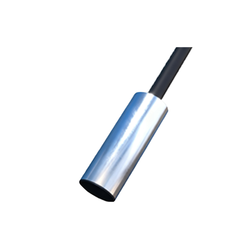
Before beginning any wiring work, it is essential to identify and understand the standard terminal markings on a 4-wire DC proximity sensor. These are typically labeled on the sensor body or within its accompanying datasheet. The most common designations are: Brown wire (or terminal +V or L+), Blue wire (or terminal 0V or L-), Black wire (output NO, normally open), and White wire (output NC, normally closed). The brown wire is universally used for the positive DC supply voltage, while the blue wire is for the common negative or ground. The black wire provides the switching signal when the sensor is activated (closing the circuit), and the white wire provides the opposite signal, opening when the sensor is activated.
Required Tools and Safety Precautions
Gather the necessary tools before starting: appropriate screwdrivers, wire strippers, a multimeter for verification, and possibly a 24V DC power supply for testing. Paramount to this process is adhering to strict electrical safety protocols. Always disconnect and lock out all power sources to the control panel or machine. Verify the absence of voltage using a multimeter. Wear appropriate personal protective equipment (PPE) such as safety glasses and insulated gloves. Carefully review the sensor's datasheet for its specific voltage range (commonly 10-30V DC), current rating, and output type (typically NPN or PNP sourcing).
Step-by-Step Wiring Procedure
First, prepare the wires by stripping a small section of insulation from the ends. Connect the brown wire from the sensor to the positive terminal of your DC power supply (e.g., +24V). Next, connect the blue wire from the sensor to the negative or common terminal (0V) of the same DC power supply. This completes the sensor's power circuit. For the output, you have a choice depending on your control logic. To use the normally open (NO) function, connect the black wire to one terminal of your load (e.g., a PLC input card or a relay coil). Connect the other terminal of that load back to the positive supply (for a PNP/sourcing sensor) or to the negative supply (for an NPN/sinking sensor). The white (NC) wire is often left unconnected if not required.
Connecting to a PLC Input Module
Integration with a PLC is a common application. For a PNP-type 4-wire sensor (sourcing), the wiring is straightforward. After connecting brown to +24V and blue to 0V, connect the black (NO) output wire directly to the designated PLC digital input point. The common terminal of that PLC input group must then be connected to 0V. This creates a circuit where, upon detection, the sensor sources +24V to the PLC input. For an NPN-type sensor (sinking), the configuration is different: the black wire would be connected to the PLC input, and the PLC input's common would be connected to +24V, as the sensor will sink current to 0V when activated.
Verification and Testing
After all connections are secure and double-checked, you can proceed to apply power. Use a multimeter to verify the voltage between brown and blue wires is within the specified range. To test the sensor's operation, bring the target object (the material it is designed to detect) within the sensor's sensing range. Observe the output. When using the black (NO) wire, you should measure the supply voltage between the black wire and blue wire when the target is present. Conversely, if using the white (NC) wire, you should measure voltage when the target is absent. Simultaneously, monitor the PLC input indicator or the load (like a pilot light or relay) to confirm correct activation.
Troubleshooting Common Issues
If the sensor fails to operate, begin troubleshooting systematically. First, re-check all wiring connections for correctness and tightness. Confirm the power supply is active and delivering the correct voltage.