Understanding Proximity Sensor Types and Mounting
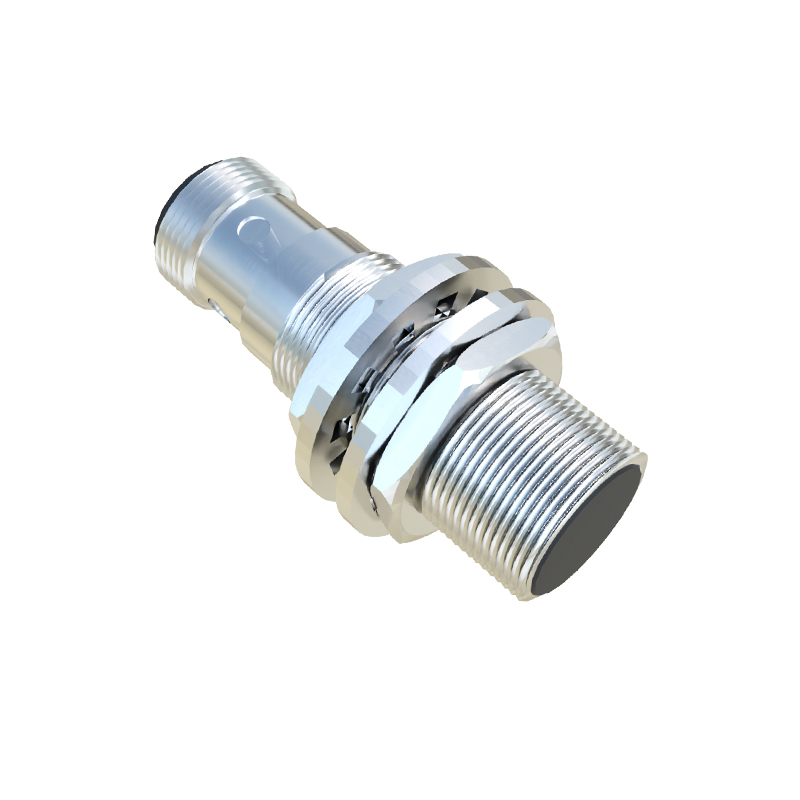
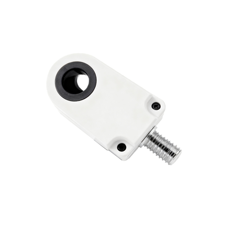
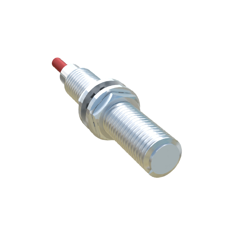
Before initiating any disassembly procedure, it is crucial to identify the type of proximity sensor you are dealing with. Common variants include inductive, capacitive, and ultrasonic sensors, each with specific mounting considerations. Inductive sensors, frequently used for metal detection, are often housed in cylindrical threaded barrels or rectangular block-style enclosures. The mounting method directly influences the removal technique. Threaded barrel sensors are typically screwed into a tapped hole, secured with a lock nut, or mounted in a bracket. Block-style sensors may be secured with bolts, slide into a DIN rail, or be part of a quick-disconnect system. Consult the sensor's datasheet or manufacturer's documentation to confirm its model, specifications, and recommended installation/removal guidelines. This preliminary step prevents damage and ensures you have the correct tools ready.
Preparing for Safe Disassembly
Safety is the paramount concern in any industrial maintenance task. Begin by following proper lockout/tagout (LOTO) procedures to isolate the electrical and mechanical energy sources connected to the sensor and the associated machinery. Verify zero energy state using appropriate testing equipment. Once the system is safely de-energized, disconnect the sensor's electrical wiring. Note the wiring configuration; taking a photograph or creating a simple diagram is highly recommended for correct reassembly. For sensors with quick-disconnect plugs, simply unplug the connector. For hard-wired sensors, you will need to disconnect the wires from the terminal block or wire leads, carefully noting the wire colors or terminal designations (e.g., Brown/+V, Blue/0V, Black/Output). Ensure the work area is clean and well-lit.
Removing Threaded Barrel Style Sensors
For the common threaded barrel sensor, the removal process is generally straightforward but requires care to avoid damaging the sensor body or its sensing face. If a lock nut is present on the exterior threads, use an appropriate wrench to loosen and remove it first. Then, using a suitable tool—often an open-end wrench or a deep socket that fits the sensor's hex flats—rotate the sensor counterclockwise to unscrew it from its mounting hole. Avoid gripping the sensor by its plastic housing or cable, as this can cause cracks or internal damage. If the sensor is stubborn due to corrosion or overtightening, apply a penetrating lubricant carefully around the threads and allow it to soak before attempting again. Do not use excessive force.
Disassembling Block Style and Bracket-Mounted Sensors
Rectangular block-style sensors are often secured with mounting bolts or screws. Locate these fasteners, which are usually found at the base or on the sides of the sensor housing. Using the correct screwdriver or Allen key, remove these fasteners completely. Some sensors may slide out of a mounting bracket or off a DIN rail once the securing clip or screw is released. For DIN rail mounts, typically a simple downward pull on the release tab at the bottom of the sensor will disengage it from the rail. Keep all removed fasteners in a secure container to prevent loss. Inspect the mounting surface and bracket for any wear or damage that should be addressed before reinstalling a sensor.
Handling Specialized and Integrated Sensor Units
Certain applications feature specialized sensors integrated into larger assemblies or with unique mounting systems. This may include sensors with built-in amplifiers, sensors in hygienic or pressurized housings, or those using bayonet-style locking rings. For these units, referencing the specific manufacturer's manual is non-negotiable. The procedure may involve releasing locking clips, unscrewing a collar, or disengaging a spring-loaded mechanism. Pay close attention to the orientation and the presence of O-rings or gaskets that provide sealing. Carefully remove and preserve these seals if they are to be reused. Integrated units may have multiple connectors; label each one clearly during disconnection.
Post-Removal Inspection and Documentation
Once the proximity sensor is removed, conduct a thorough visual inspection. Check the sensor's sensing face for buildup of dirt, metal shavings, or other contaminants. Examine the housing for cracks, dents, or signs of impact. Inspect the cable strain relief and the connector (if present) for integrity. This inspection can provide diagnostic clues about the reason for removal (e.g., failure due to environmental factors). Clean the sensor if it is to be reused or tested. Update maintenance logs with the date of removal, the reason (e.g., preventive maintenance, fault diagnosis), the sensor's condition, and any observations about the mounting location. Proper documentation is essential for asset management and troubleshooting history.