Basic Operating Principle of Capacitive Sensors
A capacitive proximity sensor operates on the principle of capacitance change. It essentially functions as an open capacitor. The sensor's active surface consists of two metallic electrodes, often arranged concentrically, which form the sensing capacitor. When no target is present, the sensor measures the capacitance to ground in its environment. This baseline capacitance is influenced by the sensor's geometry and the dielectric constant of the surrounding medium, typically air. When a target object approaches the active surface, it alters the electrostatic field. The target acts as a dielectric material, changing the overall capacitance between the electrodes. The sensor's internal oscillator circuit is designed to detect this specific change. Once the capacitance variation exceeds a predefined threshold, the sensor's output state switches, signaling the presence of the target.
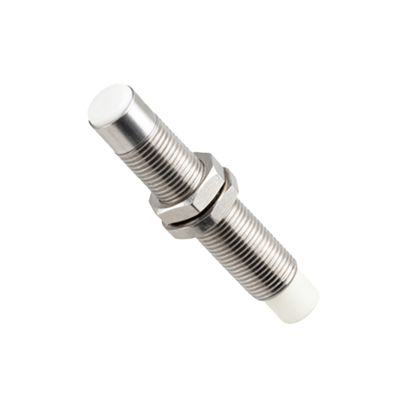
Key Structural Components
The physical structure of a capacitive sensor is engineered for sensitivity and environmental protection. The core element is the sensing electrode, usually made of a conductive material like copper or a conductive polymer. This electrode is embedded within a housing, commonly constructed from materials such as PBT (Polybutylene Terephthalate) or stainless steel for industrial durability. A critical front-end component is the dielectric face or sensing surface. This is typically a thin layer of plastic (e.g., PTFE) or ceramic that protects the electrodes from physical contact and contamination while allowing the electric field to penetrate. Internally, the electrode is connected to the oscillator and evaluation electronics. The entire assembly is often potted with a resin compound to provide mechanical stability, vibration resistance, and protection against moisture and corrosive agents.
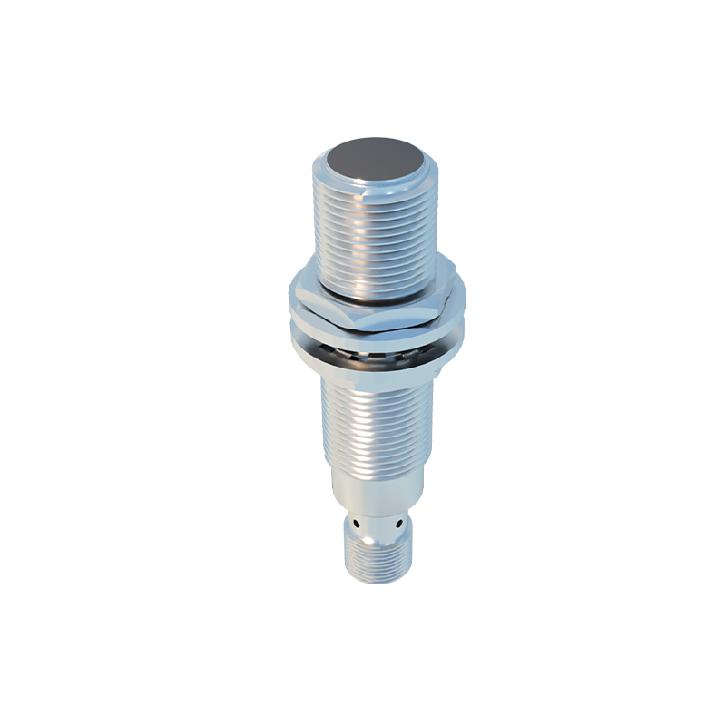
The Sensing Field and Dielectric Influence
Unlike inductive sensors, capacitive sensors generate a three-dimensional electrostatic field that projects from the active face. The shape and extent of this field are determined by the electrode geometry and the applied voltage. A key performance parameter is the sensing distance, which is nominally specified for a standard target (usually grounded steel). However, the effective sensing range is highly dependent on the target material's dielectric constant (εr). Materials with a high dielectric constant, such as water (εr ~80) or PVC (εr ~3), cause a more significant capacitance change and can be detected from a greater distance or with higher sensitivity compared to materials with a low εr, like dry wood (εr ~2). This property allows capacitive sensors to detect non-metallic objects, a distinct advantage over other proximity sensing technologies.
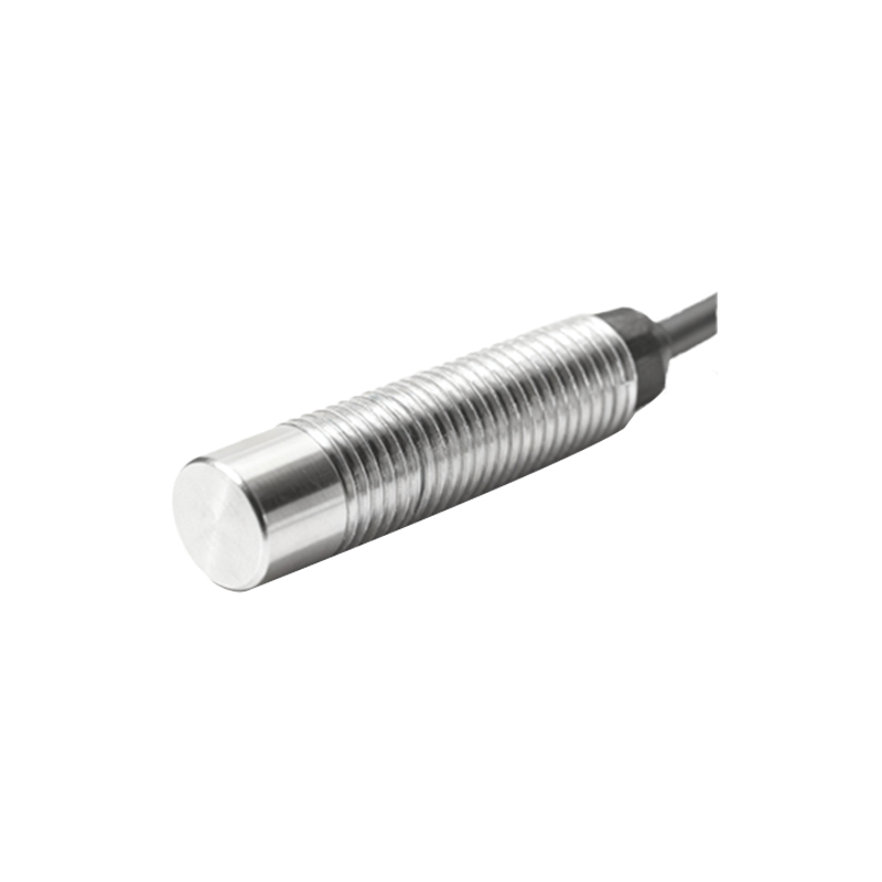
Shielding and Installation Considerations
Capacitive sensors are available in two primary structural variants: shielded (flush-mountable) and unshielded (non-flush). A shielded sensor incorporates a metallic ring or guard electrode that surrounds the main sensing electrode. This guard is driven at the same potential, which focuses the electrostatic field radially forward from the active face. This design allows the sensor to be installed flush with a metal mounting surface without the metal interfering with its operation. Unshielded sensors lack this guard ring, resulting in a larger, more expansive field that extends laterally. They offer a longer sensing range but cannot be flush-mounted in conductive material, as the surrounding metal would constantly actuate the sensor. Proper installation geometry is crucial to avoid false triggers from adjacent machinery or structures.
Internal Circuitry and Output Configuration
The structural design integrates the sensing element with sophisticated electronics. The oscillator circuit, connected to the sensing electrode, generates a high-frequency field. The evaluation circuit continuously monitors the oscillation amplitude or frequency. The sensitivity adjustment, often via a potentiometer or teach-in button, sets the detection threshold corresponding to the desired capacitance change. Once triggered, the output stage activates. Common output structures include solid-state switches (PNP or NPN transistors) for DC sensors, or relay contacts. Analog output versions (0-10V, 4-20mA) provide a signal proportional to the distance or capacitance change. The electronics are powered typically by 10-30V DC or 20-250V AC, and the entire circuit is designed for stability against temperature fluctuations and electrical noise.
Material and Housing Design for Specific Applications
The external structure is tailored to application demands. For hygienic or food-grade environments, sensors feature polished stainless steel (AISI 316L) housings with smooth contours to prevent bacterial growth and allow for easy cleaning. Chemical-resistant variants use housings and face materials like PVDF. In bulk level detection applications, sensors may have elongated or rod-shaped probes to project the sensing field into a tank. High-temperature versions employ specialized high-temperature resins, ceramics, and high-temperature solder to maintain integrity. The IP (Ingress Protection) rating, such as IP67 or IP69K, defines the structural sealing effectiveness against dust and water, dictating gasket design, cable gland selection