Understanding Photoelectric Sensor Fundamentals
Photoelectric sensors are indispensable components in modern industrial automation, providing non-contact detection of objects. They operate by emitting a beam of light (visible red, infrared, or laser) and detecting changes in the received light intensity. The core types include through-beam, retro-reflective, and diffuse reflective sensors. Each type has distinct wiring and installation considerations. Before connecting any sensor to a PC, it is crucial to understand its output configuration. Common output types are NPN (sinking) and PNP (sourcing) transistor outputs, as well as analog (0-10V, 4-20mA) and relay contact outputs. The sensor's datasheet is the ultimate authority for its electrical characteristics, including voltage requirements, output current, and wiring diagrams. Mismatching power supplies or incorrectly connecting load wires can lead to immediate device failure or erratic operation.
Essential Hardware and Interface Components
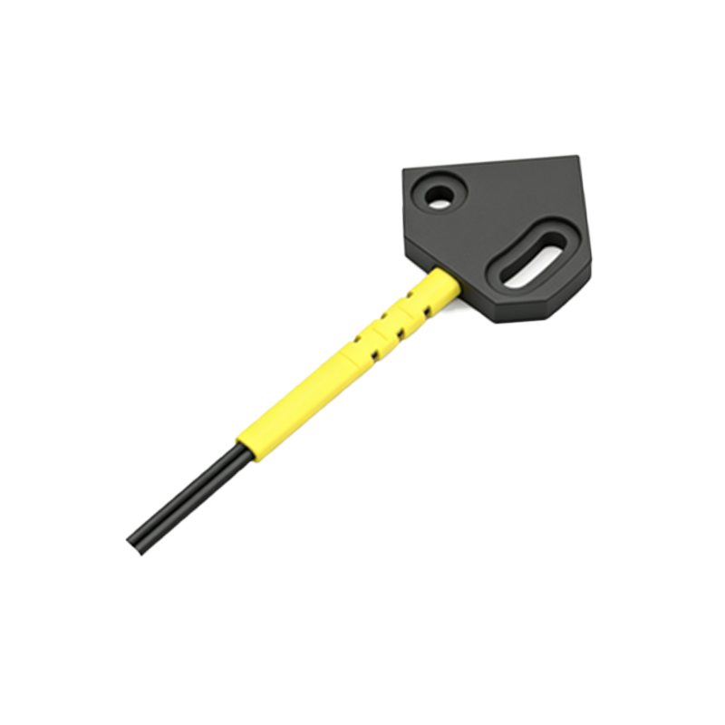
Directly wiring a photoelectric sensor to a standard PC is not feasible due to the voltage and signal level mismatch. Therefore, an interface device is mandatory. The most common solution is a programmable logic controller (PLC) with communication modules (e.g., Ethernet/IP, Profinet, Modbus) that link to the PC. For simpler or prototyping applications, digital I/O (Input/Output) interface cards are highly effective. These cards, often connected via USB, PCI, or Ethernet, provide multiple channels of isolated digital inputs that can accept the sensor's switched signal. For analog sensors, a data acquisition (DAQ) device with analog input channels is required. Additionally, you will need a suitable DC power supply (typically 12-24VDC) for the sensor, appropriate gauge wiring, and possibly signal conditioning modules like opto-isolators to protect your PC interface from electrical noise and voltage spikes common in industrial environments.
Wiring a Digital Output Sensor to a PC Interface
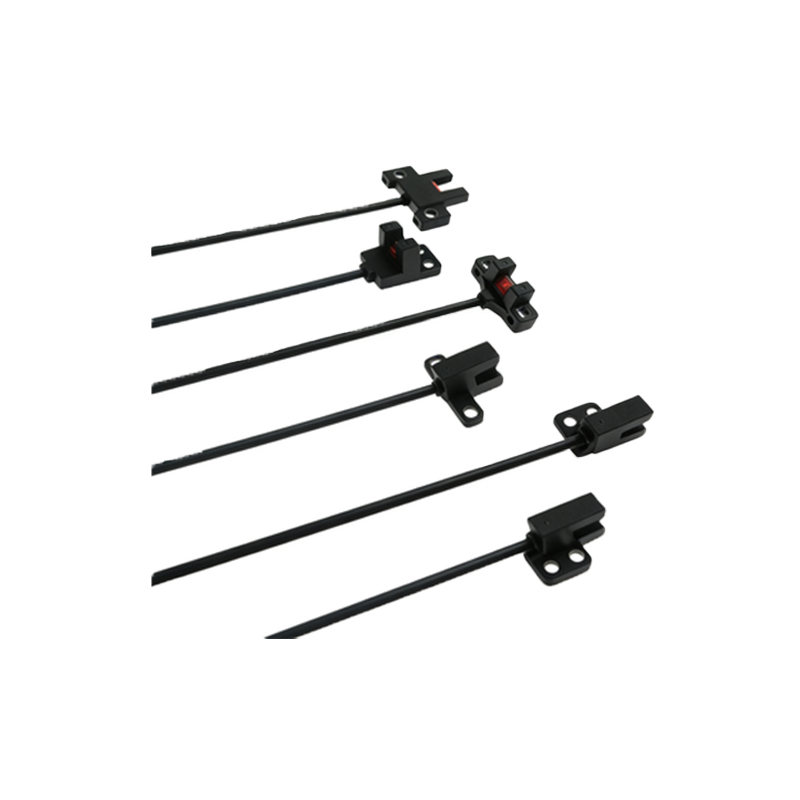
The process for a standard 3-wire DC sensor (with NPN output) is outlined here. First, ensure all power is OFF. Connect the sensor's brown (or red) wire to the positive terminal of your 24VDC power supply. Connect the sensor's blue (or black) wire to the negative terminal of the same supply. This powers the sensor's internal circuitry. The sensor's black (or white) wire is the switched output. For an NPN sensor, this wire will connect to the digital input channel on your I/O card. The digital input channel itself must be provided with a voltage reference. Typically, you connect the positive terminal of the same 24VDC supply (or a separate 5-24VDC source, as per the I/O card specs) to the common positive of the input group. The I/O card input will close the circuit to ground internally. When the sensor detects an object, its NPN transistor activates, connecting the black output wire to the sensor's internal ground (blue wire), thus allowing current to flow into the I/O card input and signaling a logic HIGH or LOW state to the PC software.
Configuring Software and Establishing Communication
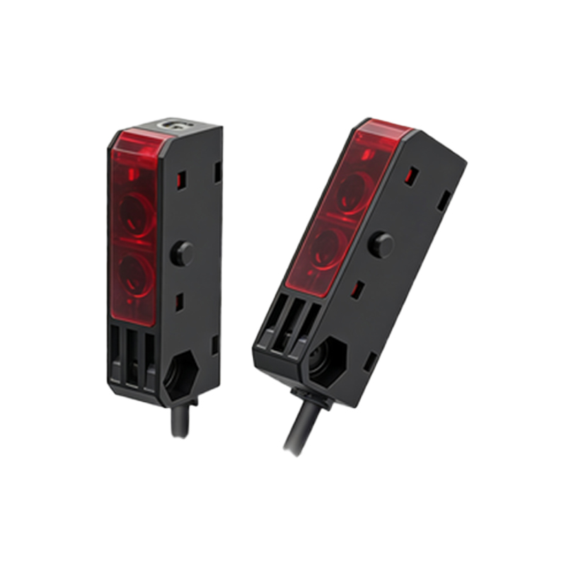
With the hardware wired correctly, the next critical phase is software configuration. For a digital I/O card, install the manufacturer's provided drivers and application programming interface (API) or use supported software like LabVIEW, Python with libraries (e.g., PySerial, pylibnidaqmx), or C#. The software must be configured to recognize the specific hardware model and map the physical input channel you used to a software variable. You will typically set the input type (sinking or sourcing) to match your wiring. For PLC-based systems, you must program the PLC ladder logic to read the sensor's input and then use the PLC's communication protocol (e.g., OPC UA, Modbus TCP) to transfer that data to a supervisory SCADA or HMI software running on the PC. Testing is vital: use the software's diagnostic tools to monitor the input state while physically interrupting the sensor's light beam to verify a clean, bounce-free signal transition.
Troubleshooting Common Wiring and Signal Issues
Even with careful planning, issues can arise. If the sensor indicator LED activates but the PC software does not detect a signal, first verify the I/O card's power and grounding. Use a multimeter to check for the presence of the switched voltage (e.g., 24V to 0V) at the I/O card terminals when the sensor activates. Ensure the sensor's load (the I/O card input) is within its maximum current rating. For erratic signals or false triggers, electrical noise is a prime suspect. Implement best practices: use shielded cables for the sensor output, ground the shield at only one end (usually the power supply end), keep sensor wiring separate from high-voltage AC lines, and consider using ferrite cores on cables near drives or motors. For persistent noise, an external signal conditioner or relay module can provide robust isolation. Always double-check for loose connections, incorrect wire strippings causing shorts, or voltage supply fluctuations.