What is Frequency Response?
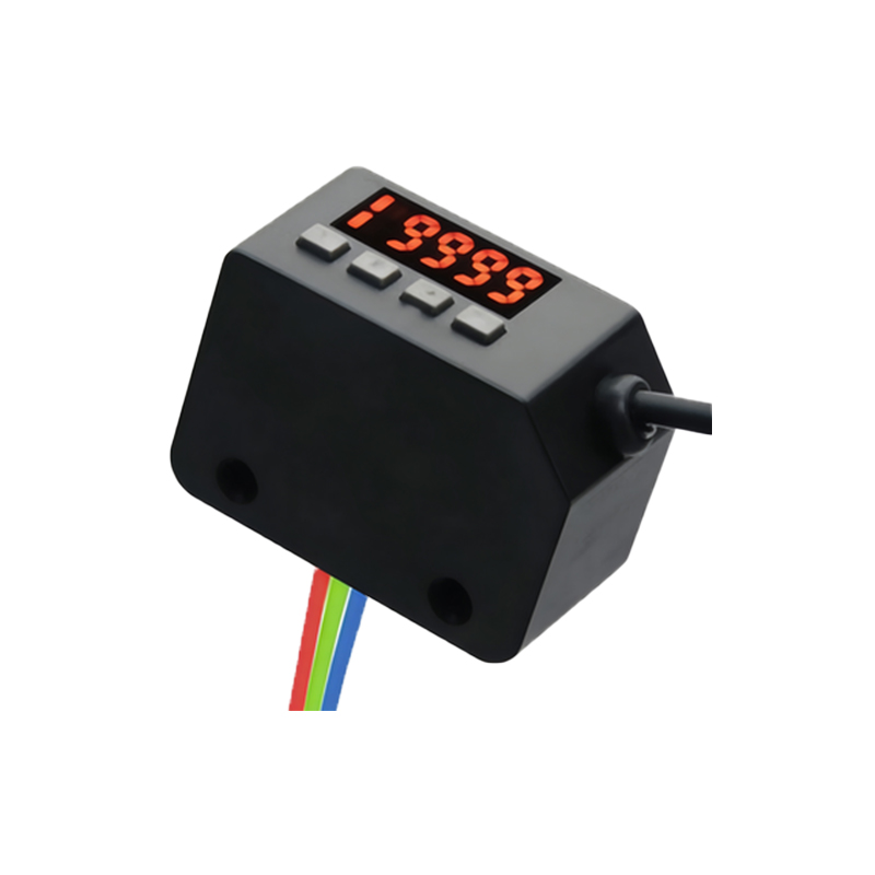
Frequency response is a critical performance parameter for photoelectric sensors, defining the maximum speed at which a sensor can reliably detect objects. It is measured in Hertz (Hz), representing the number of detection cycles (on/off operations) the sensor can perform per second. In practical terms, a sensor with a frequency response of 1 kHz can theoretically detect up to 1,000 objects passing by per second. This specification is paramount in high-speed automation, packaging, and sorting lines where rapid and accurate object detection directly impacts throughput and system efficiency. The frequency response is not a standalone figure; it is intrinsically linked to the sensor's internal circuitry, light source modulation, and signal processing algorithms. A higher frequency response indicates a faster sensor capable of tracking smaller, faster-moving objects without missing detections, which is essential for maintaining precision in modern manufacturing environments.
Key Factors Influencing Frequency Response
Several technical factors determine the achievable frequency response of a photoelectric sensor. First, the type of light source plays a significant role. Modern sensors predominantly use LEDs, and the modulation frequency of this LED is a primary determinant. Sensors often use a pulsed LED light modulated at a specific high frequency. The receiver is tuned to this frequency, allowing it to ignore ambient light and electrical noise, thereby enabling faster and more stable switching. Second, the response time of the photodetector (phototransistor or photodiode) and the subsequent amplifier circuit is crucial. Faster electronic components can process the received light signal more quickly. Third, the sensing mode is influential. Through-beam sensors, with separate emitter and receiver, typically offer the highest frequency response as they receive a strong, uninterrupted signal. Diffuse and retro-reflective modes, which rely on reflected light, often have lower response times due to weaker signal strength and more complex signal processing to overcome background interference.
Relationship Between Response Time and Frequency
Frequency response and response time are two sides of the same coin. Response time is usually specified as the time the sensor takes to turn its output on or off after a detection event occurs. It is commonly measured in milliseconds (ms). The theoretical maximum frequency response can be approximated from the total response time (Ton + Toff). For instance, if a sensor has a turn-on time of 0.1 ms and a turn-off time of 0.1 ms, the cycle time is 0.2 ms. The maximum switching frequency is then calculated as 1 / 0.002 seconds = 500 Hz. It is vital to consult the sensor datasheet, as manufacturers define and test these parameters under specific conditions. Engineers must ensure the sensor's response time is significantly shorter than the interval between passing objects to guarantee reliable detection without false triggers or missed counts.
Application Considerations and Selection Criteria
Selecting a sensor with an appropriate frequency response requires careful analysis of the application. Key questions include: What is the maximum speed of the object? What is the smallest object size? What is the required detection distance? For example, detecting small electronic components on a high-speed conveyor may require a sensor with a 5 kHz response or higher, while detecting large pallets on a slower line might only need 100 Hz. Other practical factors can limit the effective frequency. These include the sensing distance (longer distances can reduce effective speed due to light travel and beam spread), the object's surface characteristics (highly reflective or dark surfaces affect signal strength), and environmental contaminants like dust or oil fog which can attenuate the light beam. Always incorporate a safety factor, choosing a sensor with a frequency response 1.5 to 2 times higher than the calculated minimum requirement to account for real-world variances and future line speed increases.
Testing and Verifying Frequency Performance
Verifying a sensor's frequency response in the actual application is a best practice. This can be done using a rotating disk with slots (an encoder wheel) or by using the target object itself on a test rig. By gradually increasing the rotational speed or conveyor velocity and monitoring the sensor's output with an oscilloscope or high-speed counter, engineers can identify the point at which the sensor begins to miss detections or produce an unstable output. This practical test accounts for all installation variables. Furthermore, modern programmable logic controllers (PLCs) often have high-speed counter input modules designed to work with fast-switching sensors. Ensuring compatibility between the sensor's output type (PNP/NPN, push-pull, etc.) and the input module's specifications is essential to fully utilize the sensor's frequency capability without being limited by the control system's input filtering or scan time.