Understanding the Core Challenge
Connecting a 36V-rated proximity sensor to a 24V DC power supply is a common scenario in industrial automation, often driven by equipment upgrades, sensor availability, or system voltage standardization. The primary concern is not the lower voltage itself, but ensuring the sensor receives sufficient voltage to operate reliably within its specified parameters. A 36V sensor typically has a wide operating voltage range, such as 10-36V DC or 20-36V DC. A 24V supply falls within the lower end of this spectrum for many models, but this requires careful verification and potential adjustments to guarantee stable performance, signal integrity, and long-term sensor health.
Critical Pre-Connection Checks
Before making any physical connections, thorough preparation is essential. First, locate the sensor's datasheet or nameplate. Identify the exact operating voltage range (e.g., 10-30V DC, 20-36V DC). If the range explicitly includes 24V (e.g., 10-36V DC), direct connection is typically feasible. Next, determine the sensor type: PNP (sourcing) or NNP (sinking), and the output configuration (normally open/closed). Verify the current consumption of the sensor. Crucially, assess the load you are connecting the sensor to, such as a PLC input module. Confirm the PLC input's voltage compatibility and impedance. A mismatch here, especially with a lower voltage signal, can lead to unreliable switching or failure to trigger the PLC.
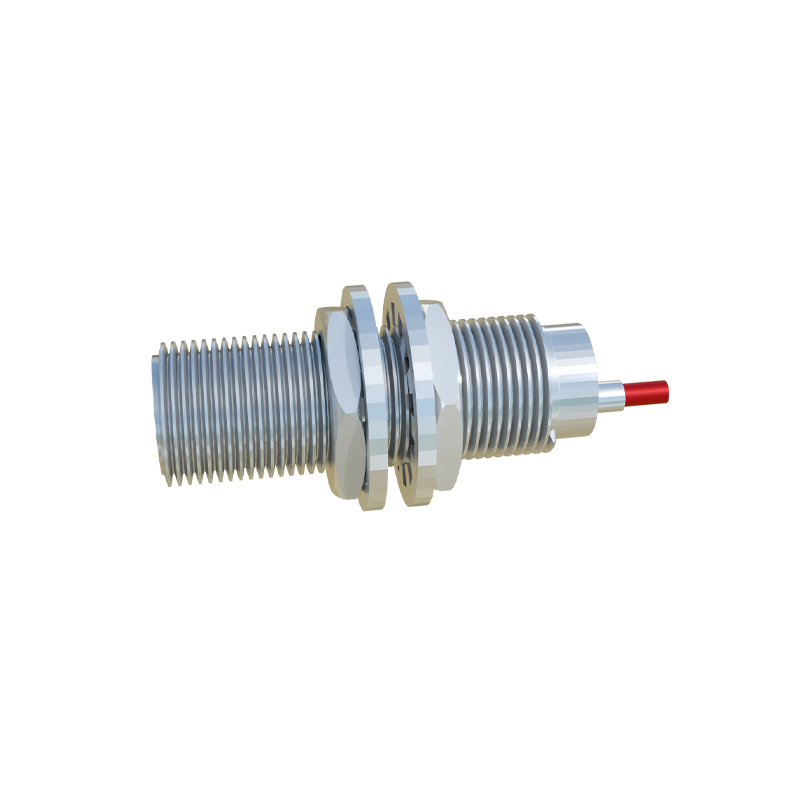
Direct Connection and Performance Implications
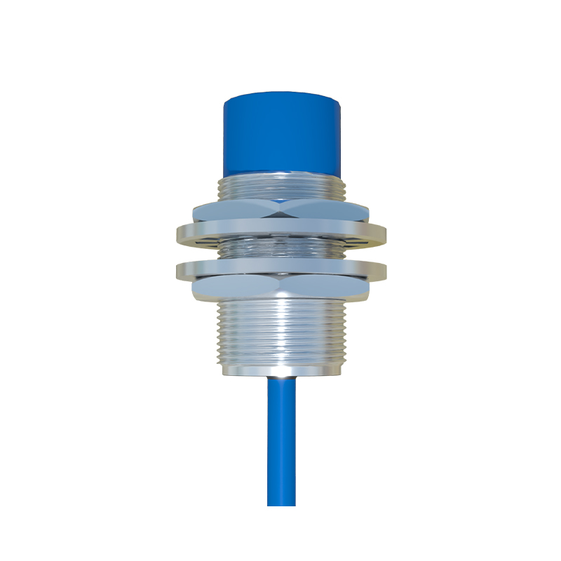
If the sensor's specified voltage range includes 24V, you can proceed with a direct connection. Wire the brown (or red) lead to the 24V DC positive terminal, the blue (or black) lead to the 0V/common terminal, and the black (or white) output wire to your load (e.g., PLC input). The load's return is then connected to 0V. However, operating at 24V instead of a nominal 36V can have implications. The sensor's sensing distance may slightly decrease. The output signal voltage, when active, will be closer to the supply voltage (around 24V), which must still meet the minimum "ON" state voltage requirement of your PLC (often 15V or higher). Ensure there is minimal voltage drop in the wiring by using proper gauge cables and secure connections to maintain voltage at the sensor.
Utilizing a Series Resistor for Current Limiting
In cases where the sensor's minimum operating voltage is above 24V, or if you need to fine-tune performance, a series resistor can be considered. This method is less common for simple voltage reduction but can help limit inrush current. A more frequent application involves the output circuit. If connecting the sensor's output to a PLC input with an internal pull-up resistor, you may need to add a series resistor to ensure the voltage divider created does not drop the signal below the PLC's logic high threshold. The value must be calculated based on the sensor's output transistor saturation voltage, the PLC input's impedance, and the required current. Incorrect resistor selection can lead to insufficient output voltage or excessive heat dissipation.
Implementing a DC-DC Step-Up Converter
For optimal and guaranteed performance, especially with sensors that have a narrow voltage range starting near 24V, using a DC-DC step-up (boost) converter is the most reliable solution. Select a compact, industrial-grade converter that takes your 24V supply input and provides a stable, regulated 36V output. Connect the 24V supply to the converter's input terminals, and then power the sensor from the converter's 36V output. This ensures the sensor operates at its nominal voltage, maintaining full specified sensing distance and robust output signal levels. Choose a converter with adequate current rating (exceeding the sensor's consumption) and protection features like over-current and short-circuit protection for system durability.
Verification and Troubleshooting Steps
After installation, systematic verification is key. Use a multimeter to measure the voltage at the sensor's power terminals under load to confirm it is within the acceptable range (e.g., 23-25V). Activate the sensor by introducing a target metal object. Measure the output voltage in both inactive and active states. The active output should be within a few volts of the supply voltage. Monitor the system for intermittent operation, which may indicate voltage drop or insufficient signal strength at the load. Check for excessive sensor heating. Always consult the manufacturer's technical support for model-specific guidance if uncertainties persist, as internal circuitry designs can vary significantly between different sensor families.