Understanding Proximity Sensor Fundamentals
Before initiating the installation process, a thorough understanding of the selected proximity sensor is paramount. Proximity sensors, including inductive, capacitive, and photoelectric types, operate on distinct principles. Inductive sensors detect metallic objects, capacitive sensors sense both metallic and non-metallic materials, and photoelectric sensors utilize light beams. The correct sensor type must be chosen based on the target material, required sensing distance, and environmental conditions such as temperature, humidity, and potential contaminants. Always consult the manufacturer's datasheet for specific specifications regarding nominal sensing distance (Sn), operating voltage, output type (PNP/NPN, NO/NC), and housing material. This foundational knowledge prevents selection errors that lead to installation failures.
Pre-Installation Planning and Site Assessment
Effective installation begins with meticulous planning. First, confirm the physical and electrical characteristics of the mounting location. Ensure there is adequate space for the sensor body and its connector or cable outlet. Check for potential interfering objects within the sensor's field of view, as other metal parts, strong electromagnetic fields, or adjacent sensors can cause false triggering. The mounting bracket or fixture must be rigid and vibration-resistant to maintain precise alignment. Verify the power supply characteristics match the sensor's requirements (e.g., 10-30V DC). Additionally, plan the cable routing path to avoid sharp bends, excessive tension, and areas with high mechanical wear or exposure to oils and chemicals.
Mechanical Mounting and Alignment Procedures
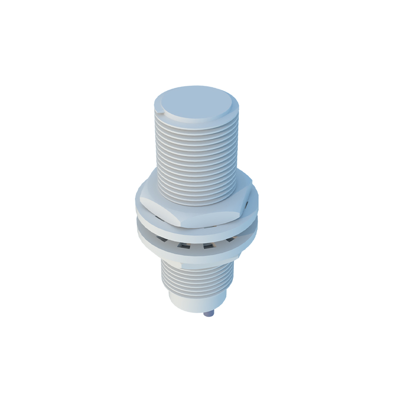
Secure mechanical mounting is critical for reliable operation. For cylindrical sensors, use the appropriate locknut and washer, tightening it to the specified torque to prevent loosening from vibration without damaging the housing. For rectangular or block-style sensors, utilize the provided mounting holes with suitable screws. The most crucial step is precise alignment. The sensing face must be positioned perpendicular to the expected path of the target object. For inductive sensors, ensure the target approaches the active face directly. Maintain the recommended installation distance, typically 0.8 times the nominal sensing distance (0.8 x Sn), to account for manufacturing tolerances and temperature drifts. Use a non-metallic feeler gauge or the actual target to fine-tune the position before final tightening.
Electrical Wiring and Connection Guidelines
Correct electrical wiring ensures both functionality and safety. Always disconnect power before making connections. Identify the sensor's wire colors or terminal designations as per the manual: typically, brown for DC+, blue for DC-, and black (or white) for the output signal. For 3-wire DC sensors, strictly adhere to PNP (sourcing) or NPN (sinking) wiring schemes to match the controller's input card (sinking or sourcing). Use shielded cables in environments with electrical noise and ground the shield at the controller end only. Protect the wiring with conduit in harsh environments. For 2-wire AC/DC sensors, ensure the load (e.g., relay coil, PLC input) is connected in series. After wiring, double-check all connections for tightness and correct polarity.
Configuration, Testing, and Commissioning
After mechanical and electrical installation, configuration and testing are essential. Some sensors feature adjustable sensing distance or sensitivity potentiometers. Set these according to the application needs, often starting at the midpoint. Power on the system and perform a functional test. Use the actual target material to verify the sensor triggers reliably at the maximum required distance. Check for false triggers by moving non-target objects nearby. Observe the sensor's indicator LED (if present) for proper on/off states. For critical applications, perform a long-duration test under normal operating conditions to ensure stability. Document the sensing distance achieved and any settings adjusted for future maintenance reference.
Common Installation Pitfalls and Troubleshooting
Awareness of common errors accelerates troubleshooting. A frequent issue is insufficient sensing distance, often caused by using the wrong sensor type (e.g., inductive sensor for a plastic target) or incorrect alignment. Ensure the target material and size meet the sensor's specifications. Electrical problems like no output or erratic behavior can stem from incorrect voltage, wiring faults, or excessive load current. Verify voltage at the sensor terminals. Noise interference may cause sporadic triggering; solutions include using a shielded cable, installing a ferrite core, or adding a noise filter. Physical damage from over-tightening, chemical corrosion, or cable stress are also common. Regular inspection as part of preventive maintenance can catch these issues early.
Maintenance and Best Practices for Longevity
Proper installation extends to ongoing maintenance. Periodically inspect the sensor for physical damage, accumulation of dirt or metal chips on the sensing face, and secure mounting. Clean the sensing face with a soft cloth and appropriate solvent if needed