Introduction to 4-Wire Photoelectric Sensors
A 4-wire photoelectric sensor represents a fundamental and widely utilized category in industrial automation. Unlike their 2-wire or 3-wire counterparts, these sensors incorporate four distinct electrical connections, which typically include two wires for power supply and two wires for the output signal. This configuration allows for a clear separation between the sensor's operating power circuit and its switching output circuit. The design offers significant advantages in terms of reliability, output options, and ease of integration into complex control systems. They are engineered to detect the presence, absence, or distance of an object using a light beam, making them indispensable for tasks ranging from simple object detection to precise positioning on high-speed production lines.
Core Operating Principle and Internal Circuitry
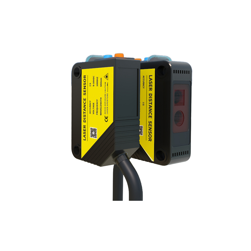
The fundamental operation hinges on the modulation and reception of light. The sensor contains a light emitter, usually an LED (infrared, red, or laser), and a photoelectric receiver (phototransistor or photodiode). The internal circuitry is more sophisticated than simpler models. The two power wires connect to a regulated internal power supply that drives the emitter and the sensor's logic circuitry. The two output wires are connected to a solid-state switching element, such as a transistor. A key feature of the 4-wire design is that the output switch is completely isolated from the sensor's internal power circuit. This often allows the output to switch a different voltage level than the sensor's supply voltage, providing tremendous flexibility. For instance, a sensor might be powered by 24V DC, but its output contacts can be configured to switch a 5V logic signal or a 120V AC load, depending on the model.
Wiring Configuration and Output Types
Understanding the wiring is crucial for correct installation. The standard color coding for DC models is: brown wire for positive supply (+V), blue wire for negative supply or common (0V), black wire for the output signal, and white wire (or sometimes another color) for a second output function or output common. The output itself can be configured in several ways. The most common is a transistor output, which can be either NPN (sinking) or PNP (sourcing). In an NPN configuration, the black wire acts as a switch to connect the load to 0V. In a PNP configuration, it connects the load to +V. The fourth wire often provides a complementary output (e.g., normally-open vs. normally-closed) or a separate common for the output circuit, enabling the aforementioned voltage isolation. Some advanced models may use the fourth wire for analog output signals (0-10V, 4-20mA) or for IO-Link digital communication.
Key Advantages Over 2-Wire and 3-Wire Sensors
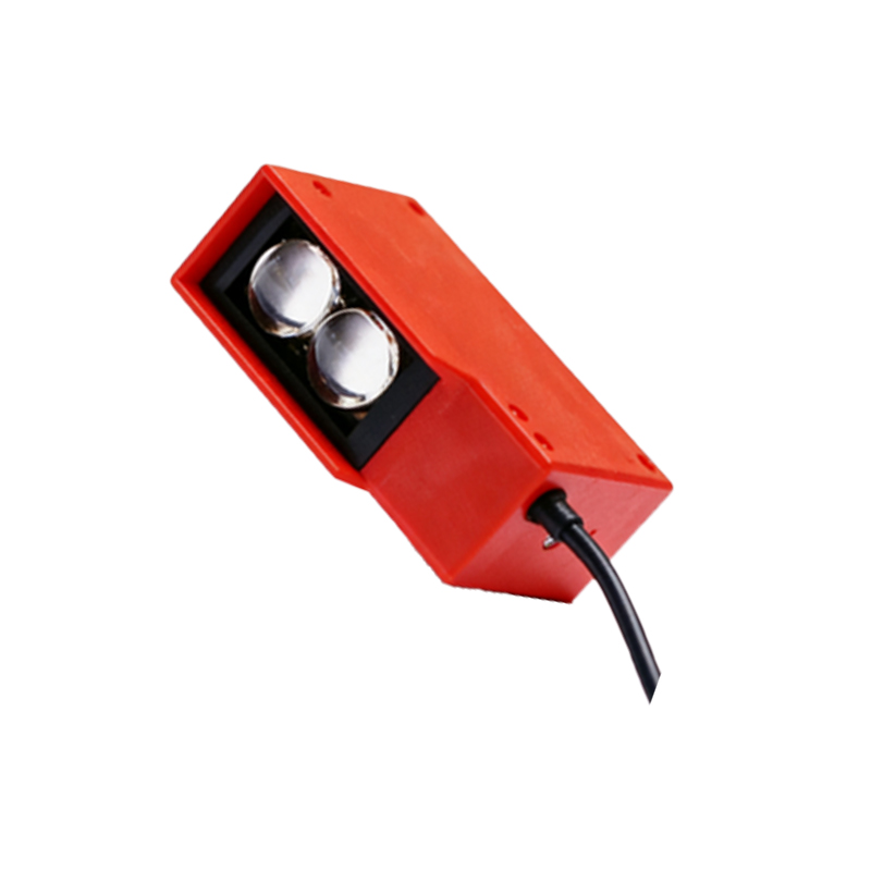
The primary benefit of the 4-wire design is electrical isolation and independent output capability. This separation prevents electrical noise from the load circuit from interfering with the sensitive sensor electronics, enhancing reliability and longevity. It also eliminates leakage current issues associated with 2-wire AC/DC sensors, ensuring a true "off" state. Compared to 3-wire sensors, the fourth wire provides greater control over the output circuit. It allows for flexible wiring schemes, such as connecting the output to a different power source, which is often necessary in PLC (Programmable Logic Controller) systems where input cards and sensor power may be on separate circuits. This design also typically supports both normally-open and normally-closed output logic without internal rewiring, simply by choosing which output wire to use.
Common Industrial Applications and Use Cases
These sensors are workhorses in virtually every manufacturing sector. Their robustness and flexible output make them ideal for: Object detection on conveyor belts for counting, sorting, or triggering subsequent actions; precise edge detection in material handling and packaging machinery; level detection in silos or tanks using reflective or through-beam methods; and part positioning in assembly robots. In automotive manufacturing, they are used to verify the presence of components. In packaging, they ensure cases are properly filled before sealing. The ability to interface directly with PLCs, motor starters, relays, and indicator lamps without additional interface modules makes them a cost-effective and reliable solution for complex automation tasks. Their long sensing range, especially in through-beam mode, is critical for large-scale material handling.
Critical Selection Criteria for Engineers
Selecting the appropriate 4-wire photoelectric sensor requires careful consideration of several parameters. First, determine the sensing mode: through-beam, retro-reflective, or diffuse (proximity). Through-beam offers the longest range and highest reliability. Next, consider the electrical requirements: supply voltage range (e.g., 10-30V DC), output type (NPN/PNP), and output current capacity. The load compatibility is vital—ensure the sensor's output can handle the current and voltage of the device it is controlling. Environmental factors are paramount: the housing material (metal or plastic), ingress protection (IP) rating for dust and water resistance, and temperature range must suit the operating environment. Finally, consider features like adjustable sensing range, built-in timers, diagnostics via LED indicators, and resistance to ambient light interference. For demanding applications, models with specialized lenses or coatings may be necessary.
Installation Tips and Maintenance Best Practices
Proper installation maximizes performance and service life. Always refer to the manufacturer's datasheet for specific wiring diagrams. Ensure the power supply is stable and within the specified range to prevent erratic operation. For through-beam sensors, meticulously align the emitter and receiver; even slight misalignment can drastically reduce effective range. Shield the sensor from harsh ambient light sources when possible. Keep lenses clean from dust, oil, and debris, as contamination is a leading cause of failure. Use mounting brackets to minimize vibration. Periodically verify the sensor's operation and check for physical damage to cables or housings. Implementing a routine maintenance schedule to clean optical components and check electrical connections can prevent unplanned downtime. Most modern sensors include a stability or signal strength indicator LED to aid in setup and troubleshooting.
Future Trends and Technological Developments
The evolution of 4-wire photoelectric sensors is closely tied to Industry 4.0 and smart manufacturing trends. Future iterations are increasingly incorporating digital intelligence. The integration of IO-Link communication as a standard feature is a significant trend, turning the traditional discrete sensor into a smart device that can transmit detailed diagnostic data (e.g., lens contamination warnings, internal temperature, signal strength) to the control system. This enables predictive maintenance. Other advancements include the miniaturization of housings without sacrificing performance, enhanced background suppression for more reliable detection of contrasting objects, and increased use of laser diodes for extremely precise detection over longer distances. Furthermore, improved resistance to electromagnetic interference (EMI) and broader operating temperature ranges continue to push the boundaries of where these reliable sensors can be deployed.